
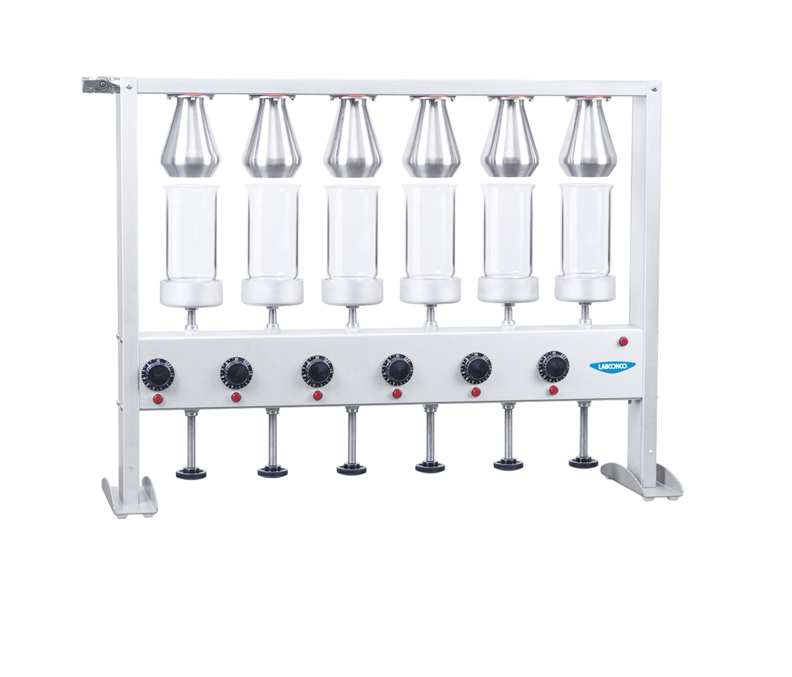
Labconco Crude Fiber Apparatus
Labconco Crude Fiber Apparatus — Kjeldahl & extraction apparatus.
The Labconco Crude Fiber Digestion Apparatus is a six-position reflux digestion unit with individually adjustable 350 W ceramic-embedded heaters and Type 304 stainless steel condensers. It is supplied in two voltage-specific configurations, 115 V/50/60 Hz/18.3 A (3000100) and 230 V/50/60 Hz/9.11 A (3000200), both without a power cord. It prepares crude fiber samples under AOAC methods, with a 6-inch exhaust manifold and 3/8" NPT water connections.
Full specifications
Description
Construction and configuration
- The apparatus is a six-position digestion bank: each position has a 350 W spring-loaded ceramic-embedded heater controlled by an individual infinite control switch (20–100% input).
- Condensers are Type 304 stainless steel; the manifold assembly terminates in a 6-inch diameter exhaust connection sized for low static pressure loss while maintaining transport velocity.
- Two factory configurations exist: Model 3000100 (115 V, 50/60 Hz, 18.3 A) and Model 3000200 (230 V, 50/60 Hz, 9.11 A). Neither includes a power cord; the main power switch must be field-wired per local electrical codes.
- Each unit ships with 12 × 600 ml beakers. Beaker elevation is set by a control knob that raises the beaker against the condenser head.
Behavior under load and media
- Heater output is independently adjustable at each of the six positions, allowing reflux rate to be tuned per sample or method; water flow through the condensers is regulated by a needle valve.
- Cooling water enters at a 3/8" NPT inlet (upper left) and exits at a 3/8" NPT outlet (upper right) to an open drain of at least 1/2" NPT, so flow can be visually confirmed.
- Material compatibility is limited to substances compatible with Type 304 stainless steel condensers.
Installation, control and operation
- Electrical supply and branch protection must be sized for 18.3 A (115 V model) or 9.11 A (230 V model); field wiring to the main power switch is required.
- Start-up check-out requires all heater control switches to be turned on to verify all circuits and pilot lights.
- Routine operation: turn on cold water and verify flow at the drain, prepare samples per AOAC methods, place sample and digestion medium in a beaker, raise the beaker to the condenser head using the elevation control knob (turn 1/4 turn left while holding the knob; do not release until the beaker is against the condenser head), then turn the main power switch ON and follow the AOAC method for fiber determination.
- Heater and water flow rates may be adjusted to vary reflux rates.
Integration & Operating Notes
The manifold exhaust connection is 6 inches in diameter, sized for minimum static pressure loss while maintaining good transport velocity. Ducting or hood connections should be sized to this diameter to preserve exhaust performance; reducing or adapting the connection may compromise vapor removal.
During start-up and check-out, all heater control switches should be turned on to ensure proper performance. This verifies each of the six independent heater circuits and pilot lights before routine use; a position that fails to heat or indicate during this check should be investigated before samples are run.
The elevation control knob must be turned 1/4 turn to the left while firmly held, and not released until the beaker is in position against the condenser head. Releasing early or misaligning the beaker can cause spillage or poor reflux; the procedure is part of normal operation for every sample.
Replacement heating elements are 3003100 (115 V, 350 W) and 3003200 (230 V, 350 W); infinite controls are 1315400 (120 V, 15 A) and 1315500 (230 V, 15 A). Ordering the wrong voltage variant will not function correctly. Condenser gasket 3022500 is a maintenance item subject to periodic replacement.
Selection & Integration Q&A
Choose 3000100 for 115 V, 50/60 Hz, 18.3 A supplies; choose 3000200 for 230 V, 50/60 Hz, 9.11 A. Both are six-position units with identical heaters and condensers. The decision is purely the available supply voltage and branch circuit capacity, since neither includes a power cord.
Provide a 3/8" NPT cold water supply to the upper-left inlet and route the upper-right 3/8" NPT outlet to an open drain of at least 1/2" NPT for visual flow check. Exhaust ducting must match the 6-inch manifold connection to preserve transport velocity and low pressure loss.
Size the branch circuit for 18.3 A at 115 V (3000100) or 9.11 A at 230 V (3000200). No power cord is supplied; the main power switch must be wired per local electrical codes. During start-up check-out, turn all heater control switches on to verify every circuit and pilot light.
The base unit includes 12 × 600 ml beakers but no power cord. Replacement parts available separately include heating elements (3003100/3003200), infinite controls (1315400/1315500), needle valve 1351600, condenser assembly 3020800, and gasket 3022500. Filtration accessories California Modified Büchner Funnel (5510000) and Oklahoma State Filter (5521000) are optional.