
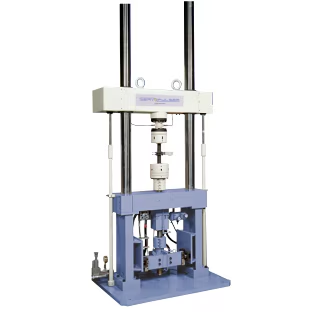
Shimadzu Axial Force AND Torsion Testing Machine
Shimadzu Axial Force AND Torsion Testing Machine — Testing machines.
The Shimadzu Axial Force AND Torsion Testing Machine is a dual-actuator test frame that applies axial force and torque simultaneously or independently to a specimen. It is intended for combined load-path testing in materials and component qualification, where uniaxial frames cannot reproduce service stress states. No further configuration, range, or interface data is available in the verified facts.
Full specifications
| Axial force: 100 kN Torsion: 1 kN-m mfr | 100 kN |
Description
Construction and positioning
- The model is a combined axial-force and torsion testing machine; the verified facts provide no frame type, actuator arrangement, or series siblings, so positioning against other Shimadzu frames cannot be stated.
- No rated capacities, torque limits, stroke, or column configuration are available; these must be obtained from the factory specification sheet before selection.
Behavior under load
- No digitized curve points, mode descriptions, or load-path data were supplied, so no statement can be made about stiffness, cross-talk between axial and torsion channels, or behavior in displacement versus load control.
Installation and operation
- No PDF digests, manuals, or interface specifications were attached; mounting, connection, control, and media requirements are therefore unspecified in this record.
Integration & Operating Notes
Because no capacity, torque, or combined-load envelope is present in the verified facts, the engineer must obtain the factory rating table and confirm that simultaneous axial-plus-torsion loading stays inside the published envelope; exceeding it risks specimen slip, grip failure, or actuator damage.
The verified facts contain no information on grip mounting patterns, specimen size range, or alignment fixtures. Selection of axial/torsion grips and any alignment couplers must be confirmed against the machine's published interface drawing before ordering.
No controller model, channel count, or transducer interface is given. The engineer must confirm how axial force, torque, and angle/extension channels are acquired and synchronized, since combined-load tests require time-aligned acquisition of both axes.
Selection & Integration Q&A
Choose it only when the specimen must see axial force and torque at the same time, as in combined-load service states. For pure tension, compression, or pure torsion, a single-axis frame is simpler; no sibling data is available here to name a specific alternative.
Confirm the grip interface pattern and specimen envelope, that the controller acquires axial force, torque, and angle channels time-aligned, and that load/torque transducer ranges cover the planned test. None of these values are in the verified facts, so they must come from the factory specification.
The verified facts contain no mounting, environmental, or duty-cycle data. The engineer must obtain the instruction manual to confirm floor/foundation requirements, ambient conditions, and permissible continuous versus intermittent loading before installation.
No maintenance schedule, cable set, grip set, or calibration consumable list is present in the verified facts. These must be requested from Shimadzu; assume grips, alignment fixtures, and calibration items are not included until the delivery scope is confirmed.