
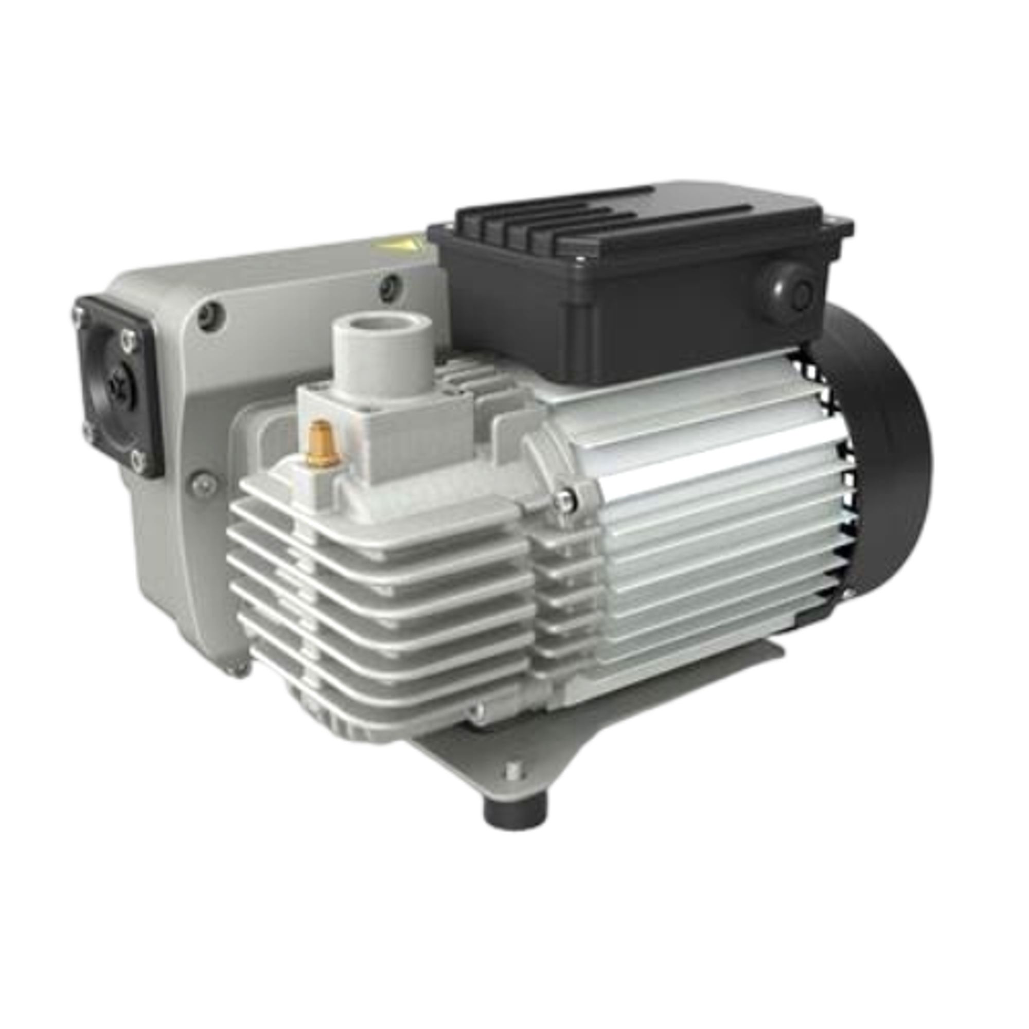
Elmo Rietschle V-VGD
Elmo Rietschle V-VGD — Central Industrial & Medical Vacuum Systems with Noise level 62 dB, Pumping speed 40 m³/h, Ultimate pressure 0.5 mbar.
The V-VGD is a one-step, oil-flooded rotary vane vacuum pump with an integrated motor and non-return valve, available in V-VGD 10 and V-VGD 15 sizes. It delivers 10 or 15 m³/h at 50 Hz and achieves 2 mbar (abs.) in fine vacuum or 10 mbar (abs.) in rough vacuum, selected via an adjusting bolt. It serves closed-system evacuation and continuous vacuum supply within defined intake pressure bands.
Full specifications
| Noise level | 62 dB(A) |
| Pumping speed | 40 m3/h |
| Ultimate pressure | 0.5 mbar |
| Series mfr | V-Series |
| Model mfr | V-VGD |
| Model variants covered mfr | V-VGD 10 | 15 |
| Pump type mfr | Oil-lubricated rotary vane vacuum pump |
| Operation mfr | Oil-flooded |
| Volume flow capacity range (max) (alt var) mfr | 360 m3/h |
| Motor variants mfr | IE3 and IE4 |
| Bearings mfr | Both sides of the rotor |
| Motor mounting mfr | Flange motor (standard) |
Description
Construction and series positioning
- The V-VGD is an oil-flooded rotary vane pump with rotor blades on the motor shaft; oil seals, lubricates and dissipates compression heat.
- Integrated mesh filter on suction, oil/oil-mist separator on outlet, motor fan cooling, and integral non-return valve.
- Flange-mounted motor is standard; IE3 and IE4 motor variants are available.
- Bearings are located on both sides of the rotor.
- Within the V-Series, the V-VGD 10 and 15 are the smallest documented variants (10 and 15 m³/h at 50 Hz); larger V-VGD 4/8/11/16/21 and V-VCS 40–300 models exist, but this card covers only V-VGD 10 and 15.
Behavior under load and in different modes
- Two manually selectable operating ranges: fine vacuum (2–200 mbar abs., max. final vacuum 2 mbar abs.) and rough vacuum (10–600 mbar abs., max. final vacuum 10 mbar abs.). The ranges overlap between 10 and 200 mbar abs.; the selected range determines the continuous-operation limit, and the adjusting bolt must be set accordingly.
- Continuous operation is permitted only inside the selected intake pressure band; outside it oil may leak through the outlet.
- When evacuating closed systems, the volume to be evacuated must not exceed 2% of nominal pumping capacity.
- Maximum permissible back pressure on the exhaust side is +100 mbar; no filter may be installed on the exhaust side.
- Permissible ambient and inlet temperature range is 5–40 °C (installation ambient min. +12 °C, max. +40 °C).
- Output reduction occurs above 1000 m above sea level.
Installation, connection and operation
- Set up horizontally with max. inclination 1° in all directions; secure against tipping on a level floor able to carry the weight.
- Keep cooling air inlets/outlets and maintenance access at least 30 cm from adjacent walls; avoid intake of hot exhaust air from other machines.
- Exhaust opening must not be closed or restricted; pipes screwed in by hand only; flexible connections where necessary.
- For standstill times longer than two minutes, vent the inlet line to atmospheric pressure.
- For parallel operation of multiple pumps, install an external non-return valve in the inlet line upstream of each pump.
- Motor connection by qualified electrician per EN 60204, with main switch and motor protection switch; observe ±5% voltage and ±2% frequency tolerances; check counter-clockwise rotation at the motor blower by brief start (max. 2 s).
- Set operating range with the adjusting bolt: fine vacuum = slot horizontal, turn clockwise to end position; rough vacuum = slot vertical, turn counter-clockwise.
- Check oil level at least once daily through the oil sight glass; use ISO VG 100 oil per DIN ISO 3448.
Integration & Operating Notes
Operating continuously outside the selected intake pressure band can cause oil to leak through the outlet opening. The fine vacuum range is 2–200 mbar (abs.) and the rough vacuum range is 10–600 mbar (abs.); the adjusting bolt must be set accordingly before commissioning. The ranges overlap between 10 and 200 mbar abs.; the selected range determines the continuous-operation limit.
When evacuating closed systems, the volume to be evacuated must be no more than 2% of the nominal pumping capacity. For V-VGD 10 and 15 this limits the connected volume to 0.2 m³ and 0.3 m³ respectively at 50 Hz; larger volumes require a different pump or operating mode.
The machine must be set up horizontally with a maximum inclination of 1° in all directions, secured against tipping, and placed on a level floor able to carry its weight. Exceeding this limit risks oil distribution problems and improper lubrication.
Cooling air inlets and outlets must be at least 30 cm from adjacent walls, and at least 30 cm space must be provided around the machine for maintenance. Ensure unobstructed ventilation grids and prevent intake of hot exhaust air from other machines into the cooling system.
Counter pressure on the exhaust side is permissible only up to +100 mbar. The exhaust air opening must not be closed or restricted, and no filter may be installed on the exhaust air side. Liquids must not accumulate in the exhaust line.
For standstill times longer than two minutes, the connected inlet line should be vented to atmospheric pressure. Provide an air release position (e.g. ball valve) in the inlet line to avoid oil being drawn into the evacuated system and to prevent machine damage.
For parallel operation of multiple pumps, an external non-return valve must be installed in the inlet line upstream of each pump. This prevents a switched-off pump from being damaged by the suction capacity of operating pumps.
The direction of rotation must match the arrow on the motor flange. Check by briefly starting the motor (max. two seconds); when looking at the motor blower it must rotate counter-clockwise. Wrong direction of rotation for a longer time may damage the machine.
The lubricating oil level must be checked at least once daily through the oil sight glass and topped up via the oil filler neck. Use ISO VG 100 oil per DIN ISO 3448. Oil changes and separator replacement follow the maintenance table.
Selection & Integration Q&A
Choose V-VGD 10 or 15 for 10 or 15 m³/h at 50 Hz and 2 mbar ultimate in fine vacuum. The V-VGD 4 offers 4 m³/h, while the V-VGD 21 provides 21 m³/h and 1.5 mbar. Select based on required pumping speed and ultimate pressure; all share oil-flooded rotary vane construction.
Use pipes screwed in by hand only; flexible connections if needed. Exhaust opening must not be restricted; back pressure max. +100 mbar; no filter on exhaust side. For standstill >2 min, provide inlet venting to atmosphere. For parallel pumps, install external non-return valves upstream of each pump.
Install horizontally with max. 1° inclination, on a level floor able to carry weight, secured against tipping. Keep 30 cm clearance around cooling inlets/outlets and for maintenance. Ambient and inlet temperature 5–40 °C (installation ambient min. +12 °C). Output reduces above 1000 m altitude.
Base delivery excludes lubricating oil (ISO VG 100 required), oil separator element, air filter, and external non-return valve for parallel operation. Daily oil level checks are required; oil changes and separator replacement follow maintenance table. Optional gas ballast valve and plug connection for motor are available.