No photo available yet
Agilent Technologies 7100 CE System
Agilent Technologies 7100 CE System — Capillary electrophoresis ce ms with Pumping speed 3.6×10⁻⁷ m³/h.
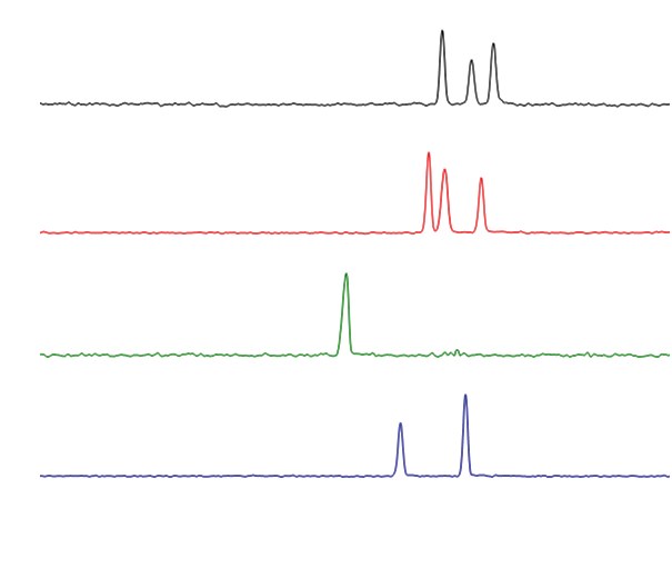
The Agilent 7100 CE System is a benchtop capillary electrophoresis instrument with a real-time UV-Visible diode-array detector (190–600 nm) and a 50-position autosampler/fraction collector. It supports pressure, electrokinetic and high-pressure injection modes, with programmable inlet pressure from -100 to +100 mbar and electrophoresis power up to ±30 kV. The system is intended for separation and quantification of charged analytes in solution, including monosaccharide determination by CE/MS/MS.
Full specifications
| Pumping speed | 6.0 µL/min |
| Sensitivity | 1 |
| Centrifugation Time | one minute |
| Detector type | MRM |
| Filter Pore Size | 0.2 μm |
| Injection modes | • Self correcting injection system with injection from inlet or outlet • Programmable range • Pressure • Electrokinetic |
| Light source | Prealigned deuterium lamp |
| Response Time | 0.063...16 s |
| Temperature range | 10...60 °C |
| Vial Volume | 100 µL |
| Background electrolyte (BGE) mfr | 0.5 |
| Separation time mfr | 14 minutes |
| Calibration range mfr | 0.02...2.0 mM |
| Calibration linearity (R2) mfr | 0.997 |
| Limit of detection (LOD, S/N) mfr | 3.4 μM |
| Capillary preconditioning - NaOH flush mfr | 5 minutes |
| Capillary preconditioning - deionized water flush mfr | 10 minutes |
| Capillary preconditioning - BGE flush mfr | 10 minutes |
| Between-run flush mfr | 60 seconds |
| Ionization mode mfr | negative negative |
| LOD Fucose mfr | 2.4 μM |
| LOQ Fucose mfr | 8.1 μM |
| LOD Galactose mfr | 1.4 μM |
| LOQ Galactose mfr | 4.6 μM |
| LOD Arabinose mfr | 1.9 μM |
| LOQ Arabinose mfr | 6.2 μM |
| LOD Glucose mfr | 1.9 μM |
| LOQ Glucose mfr | 6.2 μM |
| LOD Xylose mfr | 2.8 μM |
| LOQ Xylose mfr | 9.3 μM |
| LOD Ribose mfr | 1.2 μM |
| LOQ Ribose mfr | 3.8 μM |
| External pressure mfr | 2 bar |
| Safety standards mfr | IEC, CSA, UL UL |
| Pressure system programmable range on inlet mfr | -100 mbar |
| Flushing pressure mfr | 2...12 bar |
| Vial pressurization high pressure mfr | 2...12 bar |
| Injection mode pressure range mfr | 100 mbar |
| Injection mode maximum time mfr | 10000 seconds |
| Autosampler/fraction collector carousel mfr | 50 positions |
| Wavelength accuracy mfr | 1 nm |
| Signals mfr | eight signals simultaneously, full spectral acqu |
| Linear dynamic range mfr | 1 |
| Capillary compatibility mfr | 365 o.d. |
| Vial pressurization mfr | 2...12 bar |
| Injection mode programmable time mfr | 10000 seconds |
| Autosampler/fraction collector positions mfr | 50 positions |
| Capillary preconditioning — NaOH mfr | 0.1 minutes |
| Capillary preconditioning — deionized water mfr | 10 minutes |
| Capillary preconditioning — BGE mfr | 10 minutes |
| Inter-run flush mfr | 60 seconds |
| LOD — Fucose mfr | 2.4 μM |
| LOQ — Fucose mfr | 8.1 μM |
| LOD — Galactose mfr | 1.4 μM |
| LOQ — Galactose mfr | 4.6 μM |
| LOD — Arabinose mfr | 1.9 μM |
| LOQ — Arabinose mfr | 6.2 μM |
| LOD — Glucose mfr | 1.9 μM |
| LOQ — Glucose mfr | 6.2 μM |
| LOD — Xylose mfr | 2.8 μM |
| LOQ — Xylose mfr | 9.3 μM |
| LOD — Mannose + Fructose mfr | 1.5 μM |
| LOQ — Mannose + Fructose mfr | 5.0 μM |
| Electrophoresis power mfr | • Voltage range • Current • Power • Operation un |
| Capillary cassette mfr | High-speed forced-air cooler with Peltier elemen |
| ? mfr | Displays syntax and descriptions of commands com |
| ip <x.x.x.x> mfr | Sets new IP address address |
| sm <x.x.x.x> mfr | Sets new subnet mask mask |
| gw <x.x.x.x> mfr | Sets new default gateway gateway |
| exit mfr | Exits shell and saves all changes changes |
| Safety features mfr | Extensive diagnostics, error detection and displ |
| Control and data evaluation mfr | Agilent control software software |
| GLP features mfr | Early maintenance feedback , electronic records |
| Initialization ('init') mode mfr | 7 ON. |
| Link configuration mfr | Speed and duplex mode determined by auto-negotia |
| IP address: mfr | 192.168.254.11 |
| Subnet mask: mfr | 255.255.255.0 |
| Default gateway mfr | Not specified specified |
| OFF mfr | ON ON |
| Accessory kit mfr | 7100 |
| – HPCE startup capillary kit mfr | 1600 |
| – Coupler mfr | 0100 |
| – O-ring 25.12-mm-id 1.78-mm-XSECT-DIA mfr | 0905 |
| – O-ring 3-mm mfr | 0905 |
| – Container mfr | 1540 |
| – Air filter mfr | 3150 |
| – Tubing assembly mfr | 5063 |
| – Screwdriver, slot shaft mfr | 8710 |
| – Screwdriver, Pozidriv shaft mfr | 8710 |
| – Lift tubing assy mfr | 1600 |
| – Vial crimp/snap polypropylene 1 mL 100/PK mfr | 5182 |
| – Snap caps, polyurethane 100/PK mfr | 5181 |
| – Cable, remote mfr | 5061 |
| – Bottle, 500 mL, electrolyte, pressure plus mfr | 9301 |
| – Bottle, 100 mL, electrolyte, pressure plus mfr | 9301 |
| – Glass filter, solvent inlet mfr | 5041 |
| External pressure range mfr | 2 bar |
| Instrument mfr | 6430 LC/MS |
| Background electrolyte mfr | 0.5 |
| Ion mode mfr | ESI, negative ionization ionization |
| Drying gas flow (N2) mfr | 6 L/min |
| Nebulizer pressure mfr | 10 psi |
| Weight | 35 kg |
| Dimensions (width × depth × height) mfr | 350 mm |
| Minimum total capillary length mfr | 31 cm |
| Capillary Voltage | 4500 V |
| Power consumption | 350 BTU/h |
| Line voltage mfr | 100...240 |
| Line frequency mfr | 50 |
| Injection mode electrokinetic range mfr | 30 kV |
| – Fuse T6.3AH, 250 VAC mfr | 2110 |
| – Fuse T6.3AL, 250 VAC mfr | 2110 |
| – Fuse T3.15AL, 250 VAC mfr | 2110 |
| Applied voltage mfr | 25 kV |
| – Detector interface, green, 50 μm mfr | 7100 |
| – Detector interface, red, extended 50 μm mfr | 7100 |
| – 12 mm socket wrench mfr | 8710 |
| – LAN cable (crossover) mfr | 5023 |
| – Electrode alignment assy mfr | 7100 |
| Sheath liquid mfr | 10 TEA/methanol |
| Sheath liquid flow rate mfr | 6.0 μL/min |
| Drying Gas Temperature | 200 °C |
| Operating Altitude | 2000 m |
| Humidity mfr | 80 °C |
| External cooling mfr | 0.5 °C |
| Installation category / pollution degree mfr | 2 |
| Baseline noise mfr | 50 μAU |
| Capillary cassette cooling mfr | High-speed forced-air cooler with Peltier elemen |
| External cooling maximum pressure mfr | 0.5 bar |
| Relative standard deviation (replicate injections) mfr | 5 |
| CE specific software mfr | • Mobility report, time corrected areas, pI cali |
| Safety standards: IEC, CSA, UL mfr | Housing Housing |
| – CE System User’s Guide mfr | 7100 |
| CE Installation Qualification Kit mfr | 5063 |
Description
Construction and positioning
- Benchtop unit weighing 35 kg, requiring two-person lifting via recessed handles; bench space must allow 2.5 cm side clearance and approximately 8 cm rear clearance for air circulation and connections.
- Integrated capillary cassette with temperature control from 10 °C below ambient up to 60 °C (minimum 10 °C); accepts capillaries of 365 µm o.d. and minimum total length 31 cm.
- 50-position autosampler carousel with random access from inlet or outlet end; vial temperature control 10–40 °C requires an external water bath (minimum water bath temperature +1 °C above ambient).
- No sibling models are listed in the verified facts; this card describes the 7100 CE System only.
Behavior under load and in different modes
- Pressure system programmable on inlet from -100 to +100 mbar; flushing at 1 bar or high pressure 2–12 bar; vial pressurization 2–12 bar on inlet and/or outlet.
- Injection modes: pressure (-100 to +100 mbar), electrokinetic (-30 to +30 kV), programmable time up to 10,000 seconds.
- Electrophoresis power: voltage 0 to ±30 kV, current 0–300 µA, power 0–6 W; operation under constant voltage, current or power with programmable polarity switch.
- Detector: real-time UV-Visible diode-array, 190–600 nm, wavelength accuracy 1 nm, response time 0.063–16 s, prealigned deuterium lamp.
- For CEC or CE+p modes, an external oil-free air or nitrogen supply is required: 2–12 bar (29–174 psi) operating, maximum 15 bar (218 psi).
Installation, connection and control
- Line voltage 100–240 VAC ±10%, 50 or 60 Hz ±5%, no voltage selector; maximum power consumption 350 VA / 300 W / 1024 BTU/h.
- On-board LAN interface for PC connection; manual configuration, Bootp service, or serial RS-232C alternative for troubleshooting with Lab Advisor.
- Agilent Lab Advisor software provides diagnostics, calibration, maintenance routines and status monitoring via LAN (e.g., 192.168.254.11) or serial RS232 null-modem cable (e.g., Com1).
- Leak sensor activation triggers error LED, CE status error, logbook entry, run stop, pressure release and high voltage stop.
- To prevent blocked replenishment needle, place a vial filled with water or buffer (height 1.8 cm) in vial position 49 (home position of replenishment lift) during idle periods.
- For SDS-containing buffers, program replenishment in two steps: replenish to 0.2 cm higher than required, then fill to desired level to avoid foam interference.
Integration & Operating Notes
Insufficient clearance can cause overheating and obstruct access to the power plug. Plan bench layout so the instrument has at least 2.5 cm on either side and approximately 8 cm at the rear, and ensure the power plug remains accessible for emergency disconnection.
The instrument accepts wide-range line voltage but requires the supply to stay within 100–240 VAC ±10% and 50/60 Hz ±5%. Ensure the laboratory circuit can deliver the maximum 350 VA / 300 W and is properly grounded; no manual voltage selection is needed or possible.
During idle periods, keep a vial filled with water or buffer (height 1.8 cm) in vial position 49, the home position of the replenishment lift. This prevents buffer precipitation and blockage of the replenishment needle, which would require service intervention.
Selection & Integration Q&A
No sibling models are listed in the verified facts for this series. The 7100 CE System is the base configuration described here; selection among variants would require additional model-specific data not provided.
An oil-free air or nitrogen supply at 2–12 bar (29–174 psi) working pressure, maximum 15 bar (218 psi), is required for CEC and CE+p modes. Use appropriate regulators and filters to avoid oil contamination.
During idle periods, place a vial filled with water or buffer (height 1.8 cm) in vial position 49 (home position of the replenishment lift). This prevents buffer precipitation. No specific accessories are listed as required beyond standard vials and caps.