
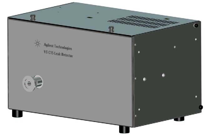
Agilent Technologies VS Series Leak Detector
Agilent Technologies VS Series Leak Detector — Liquid chromatography.
The VS C-15 is a component leak detector built around a turbomolecular-pumped spectrometer tube, connected to the user's vacuum system through a single NW25 flange. It is the base unit of the VS Series, distinguished by its 24 VDC input and reliance on an optional front panel display or host interface for operation. It serves as the leak-detection stage in vacuum system commissioning and maintenance.
Full specifications
| Gain | 1.0 decibel |
| Power cable wire gauge mfr | 18 AWG |
| Turbo speed mfr | 33000 RPM |
| Turbo life mfr | 355 Hrs |
| Ion chamber value mfr | 244.6 |
| Emission value mfr | 0.553 |
| Reject setpoint mfr | 1.0 |
| Manual tuning gain mfr | 1.0 |
| Manual tuning emission range mfr | 0.600...0.6500 |
| Manual tuning ion value target mfr | 250...270 |
| Manual tuning emission target mfr | 0.600...1.200 |
| Minimal Detectable Leak mfr | 5 sec |
| Selectable Sensitivity Ranges mfr | -3 He |
| Calibration Routine mfr | Automated or manual manual |
| Background Suppression mfr | Auto Zero and Auto Zero < Zero function function |
| Set Points (process control) mfr | Five set points: four leak rate and /or pressure |
| Discrete I/O mfr | 5 inputs |
| PUT-ION mfr | 200...350 source. |
| PUT-EMISSION mfr | 0300...2000 source. |
| ?PWDONOFF mfr | Reports status of system password . |
| ?RANGESTOP mfr | Reports the value of the Range Stop variable. va |
| ?>xREJECT mfr | Reports the reject set point is on or off . |
| ?RSONOFF mfr | Reports the status of the Range stop function as |
| SERVICE1 mfr | Displays the current status of the operating par |
| SERVICE2 mfr | Displays the current status of the operating par |
| ?SOFTSTART mfr | Returns the status of Soft Start Start |
| ?SPLITFLOW mfr | Returns the status of the split flow function, O |
| Pollution mfr | 2 Standard. |
| Foreline Pump Speed (single pump) mfr | 285 l/m |
| Foreline Pump Speed (dedicated foreline) mfr | 100 l/m |
| Power supply input mfr | 24 VDC |
| External AC-DC power supply input mfr | 100 VAC |
| Power supply voltage mfr | 24 VDC |
| AC-DC power supply input voltage mfr | 100 VAC |
| Power Input mfr | 24 A |
| Mains Supply Voltage Fluctuations mfr | 10 voltage. |
| Power Supply Voltage mfr | 24 VDC |
| Power Supply Current mfr | 5 min |
| Mains Supply Voltage mfr | 100 |
| Mains Frequency mfr | 50 |
| Maximum Test Port (foreline pressure mfr | 5 Pa |
| Display Interface (optional) mfr | High clarity TFT color touch screen screen |
| Display - Selectable languages mfr | English, French, German, Spanish, Japanese, Kore |
| Serial Interface mfr | 232 baud |
| Networking Interface (optional mfr | Profinet® I/O option option |
| INIT-DISPLAY mfr | Sets the status of the bar graph display to eith |
| Fixed Mains Socket Outlet mfr | Connect to a building protective earthing system |
| Filament 1 hours mfr | 345 hours |
| INIT-FILAMENT mfr | 1 |
| Maximum Altitude | 2000 m |
| Operating temperature | 5 °C |
| Storage temperature | -20 °C |
| Pollution degree mfr | 2 |
| Relative humidity mfr | 80 % max |
| Relative Humidity mfr | 80 % max |
| Standard leak value mfr | 1.4 |
Description
Construction and series positioning
- The VS C-15 base unit (p/n EXVSC15BU) is a self-contained spectrometer leak detector; the vacuum connection to the user system is a single NW25 flange.
- Operation and configuration are performed either through the optional front panel display unit (connected by a High Density 15-pin D-Sub cable) or through a host interface: RS-232, parallel discrete I/O, or the optional PROFINET I/O module.
- The unit is powered from 24 VDC; an optional universal external AC-DC supply (VSC15PS) allows mains operation. No sibling models are listed for this series, so the C-15 is the reference configuration.
Behavior and tuning
- Spectrometer sensitivity is optimized by manual tuning: GAIN set to 1.0, EMISSION between 0.600 and 0.6500, ION adjusted for a maximum ideally between 250 and 270, then EMISSION adjusted for a maximum ideally between 0.600 and 1.200.
- The analog output is selectable at 1 V/decade or 2 V/decade, which must match the input range of the data acquisition system.
- If the optional ConvecTorr gauge is installed it must be activated via the display or RS-232; if absent it must be deactivated, otherwise the unit remains in a System Not Ready condition.
Installation and control
- The 24 VDC supply must deliver at least 5 A, with a local branch 10 A power switch or circuit breaker; the power cable uses 18 AWG triple-twisted wires with a Molex 03-12-1036 receptacle, +24 VDC on position 1.
- With the VSC15PS option, mains input is 100–230 VAC ±10%, 50/60 Hz ±2% at a 10 A load.
- The unit is rated for pollution degree 2 and overvoltage category I; a surge protector on the 24 VDC input and, if needed for EMC, a Snap-It ferrite on the same input are recommended. After RF or ESD events the unit may need to be reset by disconnecting and reconnecting the 24 VDC supply.
Integration & Operating Notes
The base unit requires a user-provided 24 VDC source rated 5 A minimum, protected by a local branch 10 A switch or circuit breaker. Undersized supplies will not support the unit; the specified Molex 03-12-1036 receptacle with +24 VDC on position 1 must be used to preserve polarity and current capacity.
Without the optional VSC15PS universal AC-DC supply the unit cannot be connected to mains; the VSC15PS accepts 100–230 VAC ±10%, 50/60 Hz ±2% at a 10 A load. Order the supply explicitly if no 24 VDC source is available at the installation site.
If the optional ConvecTorr gauge is physically installed it must be activated via the display Advanced Parameters or via RS-232; if it is not installed it must be deactivated. A mismatch leaves the instrument in a System Not Ready condition and blocks leak detection.
The analog output is selectable at 1 V/decade or 2 V/decade. Choose the scaling that fits the connected data acquisition or PLC analog input range; a mismatch will clip or under-resolve the leak-rate signal.
The unit is rated for operation from +5 °C to +48 °C and relative humidity up to 80% max, pollution degree 2, overvoltage category I. Operation outside these limits may affect performance and safety, so ambient conditions at the installation point must be verified before commissioning.
Before any field replacement of the unit or its boards, issue the RS-232 DUMP-PARAMS command and record the output so setup parameters can be restored. SERVICE1 returns ion chamber, emission, gain, turbo speed, filament hours and calibration status for diagnostics without a front panel display.
Agilent recommends replacing all O-rings during routine maintenance or any procedure requiring disassembly. Do not use alcohol, methanol or other solvents on O-rings; vacuum grease is not recommended, and only a small amount of L grease may be applied if applicable. Use the spectrometer cleaning kit 670029096 and never Alconox on aluminum parts.
Selection & Integration Q&A
Choose the base unit when the leak detector will be driven from a host via RS-232, discrete I/O or PROFINET and a 24 VDC, 5 A source is already available at the installation point. Add the display unit if local manual tuning and valve control are needed, and the VSC15PS if only mains power is available.
A 24 VDC supply rated at least 5 A with a local 10 A branch switch, wired through the Molex 03-12-1036 receptacle with +24 VDC on position 1 using 18 AWG cable. The vacuum side connects via a single NW25 flange. Control is via RS-232, the discrete I/O connector, or the optional PROFINET module; the display unit uses a High Density 15-pin D-Sub cable.
Ambient +5 °C to +48 °C, relative humidity up to 80% max, pollution degree 2 and overvoltage category I. Fit a surge protector on the 24 VDC input and, if EMC problems appear, a Snap-It ferrite on the same input. After RF or ESD events the unit may lock up and must be reset by disconnecting and reconnecting the 24 VDC supply.
Plan O-ring replacement at every disassembly and routine maintenance, using the spectrometer cleaning kit 670029096 and avoiding solvents on O-rings and Alconox on aluminum. The 24 VDC power cable, the VSC15PS supply, the display unit, the ConvecTorr gauge, the discrete I/O board and the PROFINET module are options or user-supplied items, not part of the base unit.