
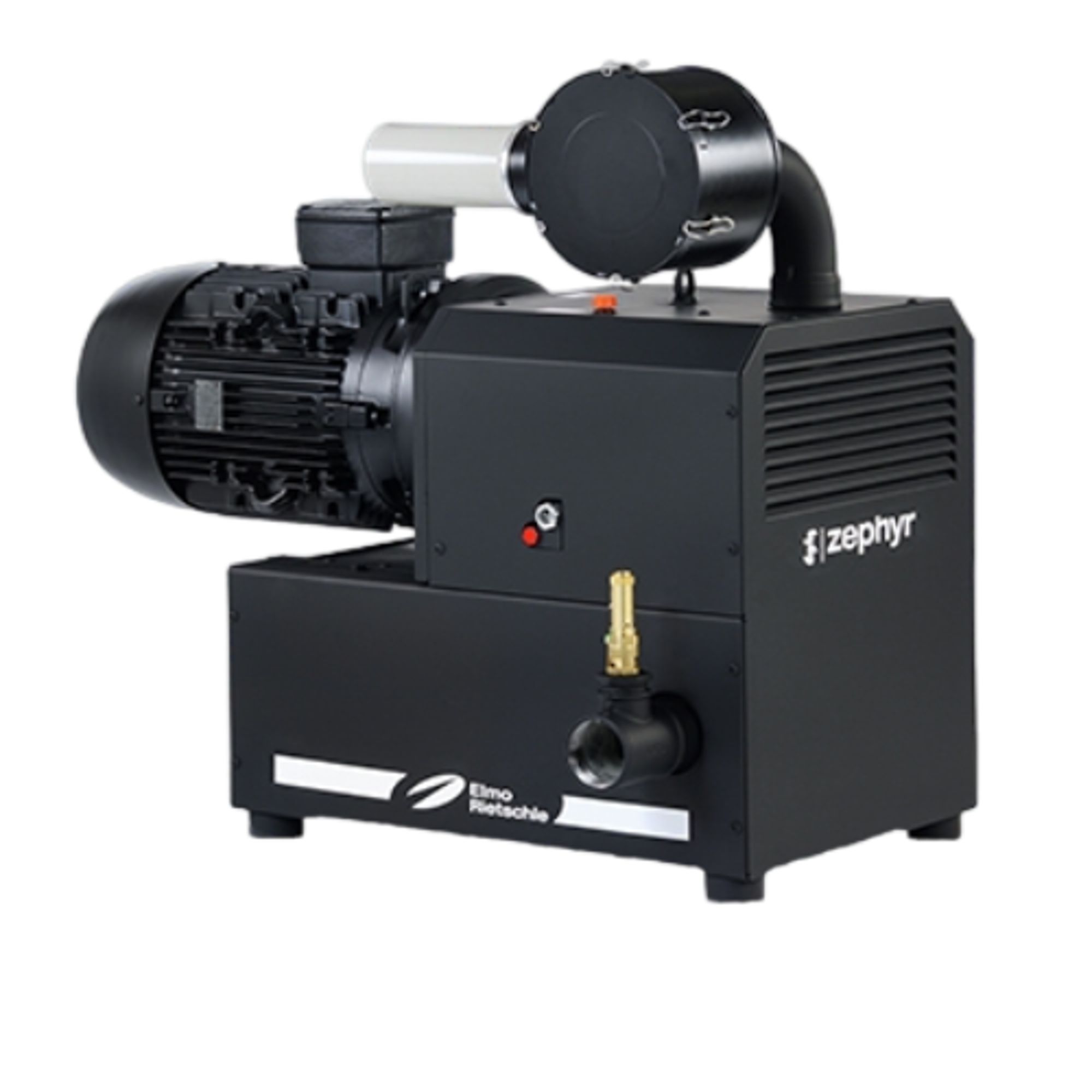
Elmo Rietschle C-DLR 301
Elmo Rietschle C-DLR 301 — Claw Vacuum Pumps with Max inlet pressure 220 kPa, Motor power 22 kW, Pumping speed 320 m³/h.
The C-DLR 301 is a double-shaft, contact-free rotary claw compressor with dry compression chamber and oil-lubricated timing gears, driven by a flanged 18.5 kW (50 Hz) / 22 kW (60 Hz) motor. It delivers 270 m³/h at 50 Hz and 320 m³/h at 60 Hz, with a maximum inlet pressure of 2.2 bar, positioning it between the C-DLR 100 and C-DLR 401 in the series. It is intended for oil-free conveyance of non-aggressive, non-toxic dry gases and gas-air mixtures in industrial vacuum/pressure systems.
Elmo Rietschle C-DLR Series — Model Comparison & Selection
Full specifications
| Max inlet pressure | 2.2 bar (50 Hz) 60 Hz: 2.2 bar |
| Motor power | 18.5 kW (50 Hz) 60 Hz: 22.0 kW |
| Operating principle | claw |
| Pumping speed | 270 m³/h (50 Hz) 60 Hz: 320 m³/h |
| Rotational speed | 2950 rpm (50 Hz) 60 Hz: 3540 rpm |
| Weight | 330 kg |
| Power supply | 400 / 690 V ± 10 % (50 Hz) 60 Hz: 380 / 660 V ± 10 % |
| Oil capacity | 1.5 l |
| Noise level | 80 dB (50 Hz) 60 Hz: 82 dB |
Description
Construction and series positioning
- Two counter-rotating claw rotors run contact-free, synchronised by an oil-lubricated gear pair in a separate gearbox; special seals isolate the dry compression chamber from the gearbox.
- Cooling is provided by a drum fan drawing air through the sound-insulating hood; the motor is flanged and coupled to the compressor shaft.
- Within the C-DLR series, the 301 sits between the smaller C-DLR 100 and the larger C-DLR 401; it shares the same dry-running claw principle but differs in displacement, motor power and connection size (G 2 discharge per ATEX documentation).
- A safety valve is fitted as standard; operation without it is not permitted.
Behaviour under load and media
- Maximum inlet pressure is 2.2 bar at both 50 and 60 Hz. For the ATEX variant, the permissible pressure/temperature envelope is defined by the T-class: T4 up to +0.8 bar/130 °C, T3 up to +1.8 bar/195 °C, T2 up to +2.0 bar/210 °C (inverter operation 25–60 Hz: T2 up to +2.0 bar/210 °C). The T-class limits therefore cap the usable inlet pressure below the mechanical maximum of 2.2 bar.
- The machine handles non-aggressive, non-toxic dry gases and gas-air mixtures; humidity is permitted but no liquids. An external inlet screen with filter unit of approx. 0.05 mm is required on the suction side.
- Rated displacement is 270 m³/h at 50 Hz and 320 m³/h at 60 Hz; actual flow depends on overpressure per data sheet D 889 (or D 887-60 for frequency converter version).
- Frequent switching (approx. 10 times per hour) or high ambient/inlet temperatures may exceed the excess temperature limit of motor winding and bearings; consult the manufacturer for such duty.
Installation, connection and operation
- Installation requires a horizontal setup with maximum inclination of 8° in all directions. Cooling air inlet and outlet must be at least 30 cm from adjacent walls; additionally, at least 40 cm free space around the machine is required for maintenance access.
- Pipes must be connected without excessive force; flexible connections (compensators) are recommended on both suction and discharge sides. No vertical exhaust lines may be installed on the discharge side due to risk of condensation. For lines longer than 3 m, a non-return valve (ZRK) is recommended to prevent reverse running after shutdown.
- Electrical connection must be performed by a qualified electrician according to EN 60204; a motor protection switch with overload-dependent turn-off delay (VDE 0660 Part 102 or IEC 60947-4-1) must be provided by the operating company. Without frequency converter, voltage tolerance is ±5 % and frequency tolerance ±2 %. With frequency converter, input is 3~ AC 400 V -15 % to 480 V +10 %, 47–63 Hz, TN/TT networks. The direct-on-line supply is 400/690 V ±10 % at 50 Hz and 380/660 V ±10 % at 60 Hz.
- Direction of rotation must be checked briefly (max. two seconds): viewed from the motor fan, it must rotate counter-clockwise. The machine may only be switched on again after it stands still.
- Oil level must be filled to the middle of the oil sight glass; oil capacity is 1.5 l. Recommended oil: ISO-VG 150 (DIN 51519), CLP HC 150, e.g. GEAR-LUBE 150.
Integration & Operating Notes
The machine must be set up horizontally on a plane, even floor and secured against tipping and falling. Exceeding 8° inclination in any direction can impair lubrication and cause damage; ensure the floor or frame is level before commissioning.
Start the motor briefly (max. two seconds) and verify that, when looking at the motor blower, it rotates counter-clockwise. Wrong direction of rotation may damage the machine. Use a phase sequence indicator. The machine may only be switched on again after it stands still.
Operation outside this range requires consultation with the manufacturer. Ensure installation room ventilation and cooling air supply are adequate. Above 1000 m above sea level, a noticeable power reduction occurs; contact the manufacturer for high-altitude installations.
Selection & Integration Q&A
Choose the C-DLR 301 when your required flow is around 270–320 m³/h and inlet pressure up to 2.2 bar. The C-DLR 100 is smaller and suited to lower flows; the C-DLR 401 is larger for higher flows. The 301 balances capacity and footprint for medium-duty dry gas handling.
Use flexible connections (compensators) on both suction and discharge sides. Install an external inlet screen with approx. 0.05 mm filter on the suction side. Avoid vertical exhaust lines on the discharge side due to condensation risk. For lines longer than 3 m, a non-return valve (ZRK) is recommended to prevent reverse running after shutdown.
Mount horizontally with max. 8° inclination in all directions. Keep 30 cm clearance for cooling air and 40 cm for maintenance. Ambient/inlet temperature must be 5–40 °C. Frequent switching (approx. 10 times per hour) or high temperatures may exceed motor winding and bearing limits; consult the manufacturer for such duty.
The base delivery does not include a motor protection switch (must be provided by the operator), an external inlet screen with approx. 0.05 mm filter, compensators, or a non-return valve (ZRK) for long lines. Spare parts are ordered per list E 887. Oil (ISO-VG 150, e.g. GEAR-LUBE 150) must be specified separately. The safety valve is included as standard and is mandatory for operation; it is a wear part and should be replaced according to the maintenance schedule.