
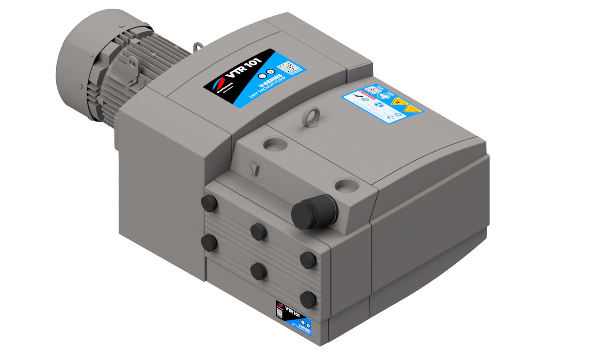
Elmo Rietschle V-VTR
Elmo Rietschle V-VTR — Central Industrial & Medical Vacuum Systems with Motor power 3.6 kW, Noise level 75 dB, Pumping speed 120 m³/h.
The V-VTR is a dry-running rotary vane vacuum pump in a close-coupled motor-pump arrangement, with a G 1 1/4 suction connection and a 3.0 kW (50 Hz) / 3.6 kW (60 Hz) three-phase motor. It delivers 100 m³/h at 50 Hz (120 m³/h at 60 Hz) and reaches an ultimate pressure of 150 mbar, intended for continuous vacuum in closed systems within the 150–1000 mbar (abs.) intake range.
Full specifications
| Motor power | 3.0 kW (50 Hz) 60 Hz: 3.6 kW |
| Noise level | 75 dB (50 Hz) 60 Hz: 77 dB |
| Pumping speed | 100 m³/hour (50 Hz) 60 Hz: 120 m³/hour |
| Ultimate pressure | 150 mbar |
| Rotational speed | 1450 rpm (50 Hz) 60 Hz: 1740 rpm |
| Suction capacity mfr | 100 m3/h (50 Hz) |
| Suction capacity mfr | 120 m3/h (60 Hz) |
| Weight | 151 kg |
| Height | 368 mm |
| Length | 842 mm |
| Width | 406 mm |
| Weight (alt var) mfr | 122 kg |
| Current | # A (50 Hz) 60 Hz: # A |
| Voltage | 230 / 400 V ± 10 % V (50 Hz) 60 Hz: 220 / 380 V ± 10 % V |
| Rated voltage mfr | 220 / 380 V ± 10 % V (60 Hz) |
| Motor rating mfr | 3.6 kW (60 Hz) |
| Inlet connection | G 11/4 |
| Protection rating | IP 55 |
| Average noise level mfr | 77 dB(A) (60 Hz) |
| Sound pressure level (max.) mfr | 82 dB(A) (50 Hz) |
| Sound pressure level (max.) mfr | 84 dB(A) (60 Hz) |
| Sound power level mfr | 92 dB(A) (50 Hz) |
| Sound power level mfr | 96 dB(A) (60 Hz) |
| Sound pressure level (max.) (alt 50 Hz) mfr | 82 dB (50 Hz) |
| Sound pressure level (max.) (alt 60 Hz) mfr | 84 dB (60 Hz) |
Description
Construction and series positioning
- The V-VTR is a dry-running rotary vane pump, close-coupled to a standard flanged three-phase motor; the pump and motor form a single unit as delivered.
- This model is the smaller of the V-VTR 100/140 pair: its pumping speed is 100 m³/h at 50 Hz (120 m³/h at 60 Hz), and its blade wear limit is >26 mm height (vs >32 mm for the V-VTR 140).
- The suction port is G 1 1/4; the unit measures 842 mm long, 406 mm wide and 368 mm high, with a maximum weight of 151 kg (base weight 122 kg).
- The motor is protected to IP 55, insulation class F, and is available for 230/400 V ±10 % at 50 Hz or 220/380 V ±10 % at 60 Hz.
Behavior under load and in different media
- The pump is designed for permanent vacuum in the intake pressure range 150–1000 mbar (abs.); the ultimate pressure is 150 mbar.
- Permissible media are air with 30–90 % relative humidity and non-explosive, non-inflammable, non-aggressive, non-poisonous dry gases and gas-air mixtures. Dust-laden, solvent-laden, oxygen, damp air, water vapour and oil-trace media are excluded. The boundary between permissible humid air (30–90 % RH) and excluded damp air/water vapour is not defined in the source; consult the manufacturer for condensing or near-saturation conditions.
- Back pressure on the outlet side must not exceed +0.1 bar; the exhaust line must be sized and routed to avoid restriction.
- Ambient and suction temperature must stay between 5 and 40 °C; operation outside this range requires consultation with the manufacturer.
- Sound pressure level (max.) is 82 dB(A) at 50 Hz and 84 dB(A) at 60 Hz, tolerance ±3 dB(A); ear protection is advised for long periods near the running machine. Average noise level is 75 dB(A) at 50 Hz and 77 dB(A) at 60 Hz.
Installation, connection and operation
- Cooling air inlets and outlets must be at least 30 cm from adjacent walls; at least 40 cm clearance is required in front of the filter housing and inlet grating for maintenance access.
- With connection pipes of the same cross-section as the machine connection and longer than 3 m, a non-return valve must be installed in the suction line to prevent reverse operation when the machine stops.
- The motor must be connected in accordance with DIN EN 60034; a motor protection switch with delayed switch-off is required. Supply deviation without derating is limited to ±5 % voltage and ±2 % frequency. The nameplate voltage tolerance is ±10 %; operation beyond ±5 % voltage requires consultation with the manufacturer for derating.
- Before commissioning, check rotation direction: looking at the motor fan, the shaft must rotate clockwise; briefly start the motor (max. two seconds) to verify. Incorrect rotation can damage or break blades.
- Pipes must be screwed in by hand only; use compatible G 1 1/4 fittings.
Integration & Operating Notes
The outlet line must be sized and routed so that back pressure never exceeds +0.1 bar. Exceeding this limit can overload the pump and invalidate the intended operating range; check the exhaust path for restrictions before commissioning.
Only air with 30–90 % relative humidity and non-explosive, non-inflammable, non-aggressive, non-poisonous dry gases or gas-air mixtures are permitted. Dust (ATEX zone 20–22), solvents, oxygen, damp air, water vapour and oil traces must be excluded from the suction stream. The boundary between permissible humid air and excluded damp air/water vapour is not defined in the source; consult the manufacturer for condensing or near-saturation conditions.
Cooling air inlets and outlets must be at least 30 cm from adjacent walls, and at least 40 cm must be left in front of the filter housing and inlet grating for maintenance. Plan the installation layout so these clearances are maintained permanently.
Looking at the motor fan, the shaft must rotate clockwise. Check by briefly starting the motor for no more than two seconds; incorrect rotation can damage or break the vanes. Use a phase sequence indicator to confirm the supply phase order.
The motor is designed for ±5 % voltage and ±2 % frequency deviation without derating. The nameplate voltage tolerance is ±10 %; operation beyond ±5 % voltage requires consultation with the manufacturer for derating before connecting the pump; otherwise motor protection may trip or the motor may overheat.
The A bearing (motor side) must be replaced after 20,000 operating hours or 2.5 years in three-shift operation. Plan this as preventive maintenance and use a qualified professional or authorised workshop for the replacement.
The B bearing (side facing away from the motor) requires 4 g of grease after 3,000 operating hours but no later than one year. Use Klüber Petamo GY193 or equivalent and do not overfill the grease reservoir.
Inspect blades first after 3,000 operating hours and thereafter every 1,000 hours. Replace the entire set if blade height falls to 26 mm or below (V-VTR 100) or thickness to 2.5 mm or below; worn blades reduce pumping capacity and can damage the pump.
Filter cartridges must be cleaned monthly by blowing from inside out and replaced every six months. Wear goggles and a dust mask when using compressed air. Maintained air filtering prevents power loss and machine damage.
Selection & Integration Q&A
Choose the V-VTR 100 when the required pumping speed is up to 100 m³/h at 50 Hz (120 m³/h at 60 Hz) and the vacuum level stays within 150–1000 mbar (abs.). The V-VTR 140 offers 140 m³/h at 50 Hz but has a larger blade wear limit (>32 mm vs >26 mm). Weight data for the V-VTR 140 is not provided in the verified facts; the V-VTR 100 has a base weight of 122 kg and a maximum weight of 151 kg.
Use compatible G 1 1/4 fittings and screw pipes in by hand only. If the suction pipe has the same cross-section as the machine connection and is longer than 3 m, install a non-return valve to prevent reverse operation when the pump stops. Ensure the exhaust line does not create back pressure above +0.1 bar.
The base delivery does not include a non-return valve, suction-line fittings, or spare filter cartridges. Plan for monthly filter cleaning and six-monthly replacement, blade inspection at 3,000 h then every 1,000 h, B-bearing greasing every 3,000 h or annually, and A-bearing replacement at 20,000 h or 2.5 years. Use Klüber Petamo GY193 grease or equivalent.