
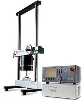
Shimadzu Micro Servo
Shimadzu Micro Servo — Testing machines.
The Shimadzu Micro Servo is a compact servo-hydraulic dynamic testing actuator delivering up to 500 N with ±10 mm piston stroke at cycle speeds to 100 Hz. Its top-or-bottom mount configuration and dual test-force/stroke control distinguish it within the series for high-cycle fatigue and dynamic characterization of small components and materials.
Full specifications
| Crosshead travel | 500 mm (EZ-SX) EZ-LX: 920 mm |
| Test force (MMT-500NV-10) mfr | Max. ± 500 N (MMT-500NV-10) |
| Test force (MMT-250NV-10) mfr | Max. ± 250 N (MMT-250NV-10) |
| Test force (MMT-101NV-10) mfr | Max. ± 100 N (MMT-101NV-10) |
| Test force (MMT-101NV-2, MMT-11NV-2) mfr | Max. ± 10 N (MMT-101NV-2, MMT-11NV-2) |
| Piston stroke (MMT-500NV-10, MMT-250NV-10, MMT-101NV-10) mfr | Max. ± 10 mm (MMT-500NV-10, MMT-250NV-10, MMT-101NV-10) |
| Piston stroke (MMT-101NV-2, MMT-11NV-2) mfr | Max. ± 2 mm (MMT-101NV-2, MMT-11NV-2) |
| Tensile test force (Tensile Test Jig) mfr | 100 N (Tensile Test Jig) |
| 3-point bending test force (3-Point Bending Test Jig) mfr | 100 N (3-Point Bending Test Jig) |
| 4-point bending test force (4-Point Bending Test Jig) mfr | 100 N (4-Point Bending Test Jig) |
| Key pressing test force (Key Pressing Test Jig) mfr | 100 N (Key Pressing Test Jig) |
| Compression test force (Compression Test Jig) mfr | 100 N (Compression Test Jig) |
| Max. test force mfr | Max. 500 N N (EZ-SX) |
| Max. test force mfr | Max. 5 kN kN (EZ-LX) |
| Max. test force mfr | Max. 2 kN kN (EZ-LX HS) |
| Test speed mfr | 0.001 to 1000 mm/min (EZ-SX) |
| Test speed mfr | 0.001 to 2000 mm/min (EZ-LX) |
| Capacity (UW220H) mfr | 220 g (UW220H) |
| Capacity (UW420H) mfr | 420 g (UW420H) |
| Capacity (UW620H) mfr | 620 g (UW620H) |
| Capacity (UW820H) mfr | 820 g (UW820H) |
| Capacity (UW1020H) mfr | 1,020 g (UW1020H) |
| Capacity (UW2200H) mfr | 2,200 g (UW2200H) |
| Capacity (UW4200H) mfr | 4,200 g (UW4200H) |
| Capacity (UW6200H) mfr | 6,200 g (UW6200H) |
| Capacity (UW420S) mfr | 420 g (UW420S) |
| Capacity (UW820S) mfr | 820 g (UW820S) |
| Capacity (UW4200S) mfr | 4,200 g (UW4200S) |
| Capacity (UW8200S) mfr | 8,200 g (UW8200S) |
| Capacity (UX220H) mfr | 220 g (UX220H) |
| Capacity (UX420H) mfr | 420 g (UX420H) |
| Capacity (UX620H) mfr | 620 g (UX620H) |
| Capacity (UX820H) mfr | 820 g (UX820H) |
| Capacity (UX1020H) mfr | 1,020 g (UX1020H) |
| Capacity (UX2200H) mfr | 2,200 g (UX2200H) |
| Total weight (MMT-500NV-10) mfr | approx. 150 kg (MMT-500NV-10) |
| Total weight (MMT-250NV-10) mfr | approx. 120 kg (MMT-250NV-10) |
| Total weight (MMT-101NV-10) mfr | approx. 100 kg (MMT-101NV-10) |
| Total weight (MMT-101NV-2, MMT-11NV-2) mfr | approx. 80 kg (MMT-101NV-2, MMT-11NV-2) |
| Frequency (MMT-101NV-2, MMT-11NV-2) mfr | Max. 60 Hz (MMT-101NV-2, MMT-11NV-2) |
| Power supply (MMT-500NV-10, MMT-250NV-10, MMT-101NV-10) mfr | 1ø 100 V 1 kVA (MMT-500NV-10, MMT-250NV-10, MMT-101NV-10) |
| Power supply (MMT-101NV-2, MMT-11NV-2) mfr | 1ø 100 V 500 VA (MMT-101NV-2, MMT-11NV-2) |
| Load cell (standard accessory) (MMT-500NV-10) mfr | ± 500 N (MMT-500NV-10) |
| Load cell (standard accessory) (MMT-250NV-10) mfr | ± 250 N (MMT-250NV-10) |
| Load cell (standard accessory) (MMT-101NV-10) mfr | ± 100 N (MMT-101NV-10) |
| Load cell (standard accessory) (MMT-101NV-2, MMT-11NV-2) mfr | ± 10 N (MMT-101NV-2, MMT-11NV-2) |
Description
Construction and positioning
- Servo-hydraulic actuator with integrated servo valve and displacement transducer; test force and stroke are the two standard controlled channels, with two additional control channels available as options. - Actuator can be mounted either top-down or bottom-up, allowing the load frame and specimen fixturing to be arranged around the actuator rather than the reverse. - Total assembly weight approximately 150 kg; installation envelope approximately 1000 × 500 × 1200 mm (W × D × H). ### Performance under load
- Rated dynamic test force 500 N; piston stroke ±10 mm; cycle speed up to 100 Hz. - Test-force indication accuracy within ±0.5 % of indicated value or ±0.02 % of maximum dynamic test force, whichever is greater. - Stroke indication accuracy within ±1 % of indicated value or ±0.1 % of maximum stroke, whichever is greater. - No digitized curve points were supplied; dynamic force-displacement behavior must be characterized on site or obtained from Shimadzu application data. ### Installation, connection and operation
- Power: single-phase 100 V, 1 kVA. - Site requirements: ambient +10 to +40 °C recommended with variations within ±5 °C, low humidity, no direct airflow from heating or cooling systems, and no direct sunlight.
Integration & Operating Notes
The actuator can be mounted either at the top or at the bottom of the load frame. Because the 150 kg assembly and its hydraulic connections are arranged around this choice, the frame, specimen fixture and service access must be designed for the selected orientation; changing orientation later requires re-plumbing and re-alignment.
The system draws 1 kVA from a 1Ø 100 V supply. A dedicated circuit rated for the full 1 kVA plus starting margin should be provided, and the supply should be free of large switched loads that could disturb the servo valve command signal during high-cycle operation.
Recommended ambient is +10 to +40 °C with variations within ±5 °C, low humidity, no direct sunlight and no airflow from HVAC outlets. Because force accuracy is ±0.5 % of reading, thermal gradients across the load cell and actuator can consume a significant part of that budget; locate the machine away from doors, windows and diffusers.
The rated dynamic test force is 500 N and piston stroke is ±10 mm. Commanding beyond either limit risks overloading the load cell or driving the piston into its mechanical stops; the control system should be configured with software limits inside these values and checked during specimen setup.
Test force and stroke are the two standard controlled items. Two additional controlled items can be added as options, so the controller and I/O plan should reserve capacity for those channels if future multi-channel control is anticipated.
Selection & Integration Q&A
A dedicated single-phase 100 V, 1 kVA circuit is required. The room must hold +10 to +40 °C with variations within ±5 °C, low humidity, no direct sunlight and no airflow from heating or cooling outlets. Plan approximately 1000 × 500 × 1200 mm of floor space and access for the 150 kg assembly.
The actuator accepts either top or bottom mounting. The load frame, specimen grips and hydraulic hose routing must be designed for the chosen orientation before delivery, because the 150 kg actuator and its connections are arranged around that decision and cannot be re-oriented without re-plumbing and re-alignment.
The base delivery covers the actuator with test-force and stroke control. Two additional controlled channels are options, and no PDF manual digests or accessory lists were supplied, so hydraulic power supply, controller, cables, grips and fixtures should be confirmed with Shimadzu as separate items.