
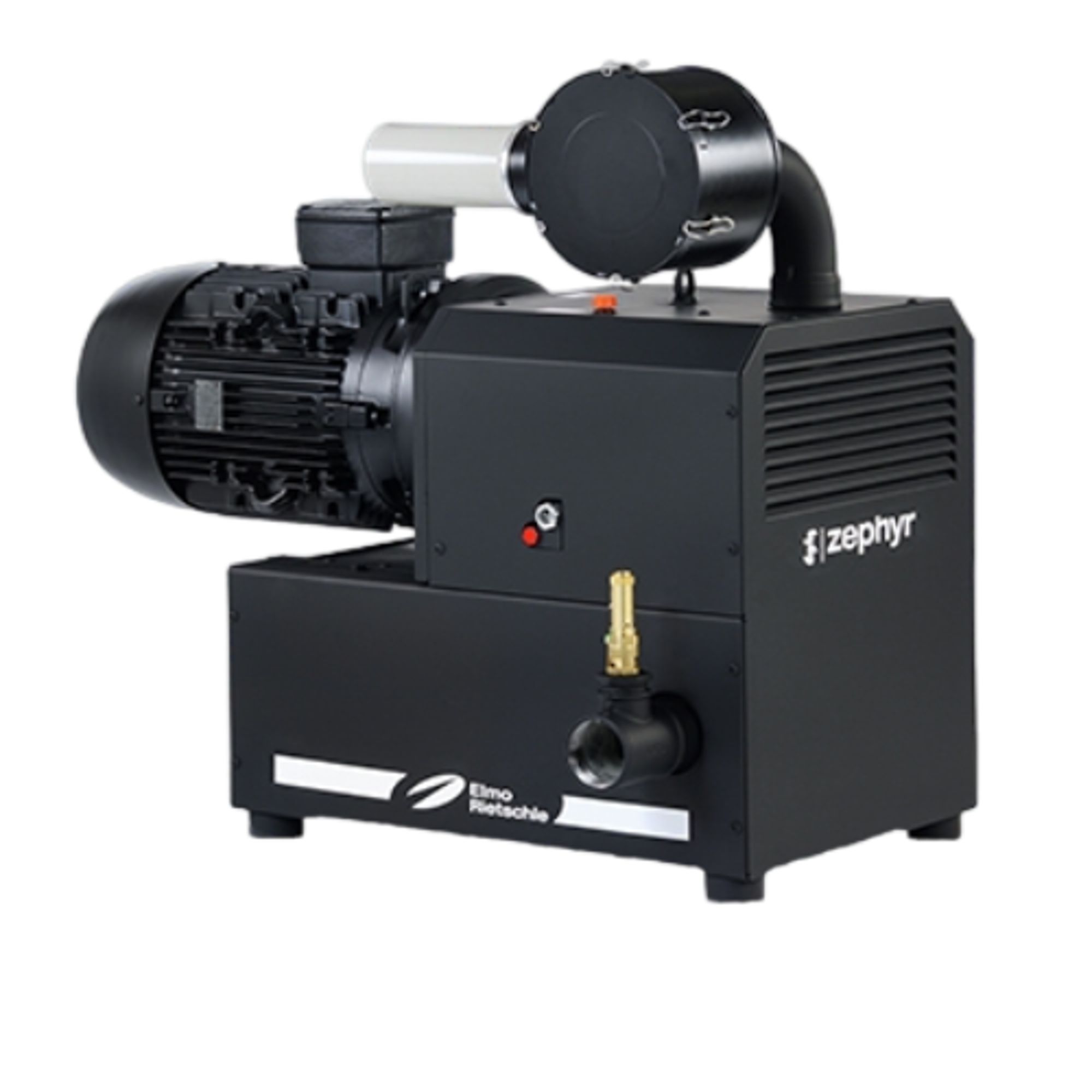
Elmo Rietschle C-DLR 401
Elmo Rietschle C-DLR 401 — Claw Vacuum Pumps.
The C-DLR 401 is a dry-running, two-shaft rotary claw compressor with contact-free rotors synchronized by an oil-lubricated gear pair, delivering 400 m³/h at 50 Hz. It is the smaller of two C-DLR sizes (401/501) and is distinguished by a 510 kg mass, 86 dB(A) sound pressure and G 3 pressure connection. It serves continuous overpressure generation in pneumatic conveying, aeration or process air systems where oil-free compression is required.
Elmo Rietschle C-DLR Series — Model Comparison & Selection
Full specifications
| Height | 1123 mm |
| Length | 1295 mm |
| Weight | 510 kg |
| Width | 742 mm |
| Outlet flange | G 3 |
| Oil capacity | 1.85 l |
| Noise level | 86 dB(A) (50 Hz) 60 Hz: 86 dB(A) |
| Sound power level mfr | 99 dB(A) (50 Hz) |
| Sound power level mfr | 99 dB(A) (60 Hz) |
Description
Construction and series positioning
- Two-shaft claw principle: rotors rotate without contact and dry; synchronization via a gear pair housed with the motor-side bearings in a common oil reservoir.
- Gear chamber and compression chamber are separated by special seals; the machine is enclosed by an insulating cover with a drum fan for cooling air.
- Within the C-DLR series, the 401 is the 400 m³/h (50 Hz) size; the sibling C-DLR 501 delivers 500 m³/h and is heavier (576 kg) and slightly larger. The C-DLR 301 (22 kW, 320 m³/h) is a smaller frame. The 401 shares design and manual with the 501 but differs in flow, weight, dimensions and sound power.
- Standard three-phase flanged drive motor, IP 55, insulation class F per DIN EN 60034; motor data on the motor data plate.
Behavior under load and media
- Permitted overpressure range is 0 to the limit marked on the data plate; continuous operation is permitted. Flow rate depends on excess pressure per data sheet D 889 (no curve points supplied here).
- Ambient and suction temperature must stay between 5 and 40 °C. Frequent switching (about 10 times per hour) or high ambient/suction temperatures can exceed motor winding and bearing temperature limits; consult the manufacturer.
- Above 1000 m above sea level a noticeable performance decrease occurs; contact the manufacturer.
- The machine is oil-free in the compression chamber; only the gear/bearing chamber carries 1.85 l of ISO VG 150 oil (Elmo Rietschle GEAR-LUBE 150).
Installation, connection and operation
- Operate only in horizontal position and never without cover plates. Floor must be flat and load-rated for 510 kg; unanchored installation on a flat surface is possible, elastic damping elements are recommended on a base.
- Cooling air inlet/outlet at least 30 cm from walls; at least 40 cm in front of the suction flange for maintenance.
- Pressure connection G 3; tighten pipes by hand only. Narrow or long pressure lines reduce flow. For lines longer than 3 m with the same cross-section, install a non-return valve (ZRK) to prevent reverse operation after shutdown.
- Safety valve is standard overload protection and must not be removed; it is a wear part replaced after 10,000 h or at latest 2 years.
- Electrical: specialized electrician per EN 60204; delayed-trip motor protection breaker recommended due to cold-start overcurrent. Verify clockwise phase sequence with an indicator; motor fan must rotate counter-clockwise when viewed at the fan (brief test max. 2 s).
- Surfaces can exceed 70 °C; hearing protection required for prolonged presence near the running machine (86 dB(A) sound pressure, 99 dB(A) sound power).
Integration & Operating Notes
The machine weighs 510 kg and must sit on a flat, straight floor whose load capacity is dimensioned for that weight. Length and weight may differ depending on motor manufacturer, so verify the actual data plate before finalizing foundation or lifting plans. Unanchored installation is allowed on a flat surface; on a base, elastic damping elements are recommended.
Operation outside 5 to 40 °C requires consultation with the manufacturer. Frequent switching (about 10 times per hour) or high ambient/suction temperatures can push motor winding and bearing temperatures beyond their limits, so the duty cycle and enclosure ventilation must be checked against these conditions.
Use a phase sequence indicator to confirm clockwise rotating field. Briefly switch on the motor (max. 2 seconds) and check that the motor fan rotates counter-clockwise when viewed at the fan. Prolonged reverse rotation can damage the machine. A delayed-trip motor protection breaker is recommended because of temporary overcurrent during cold start.
The safety valve is installed as standard overload protection and the machine must not be operated without it. It must be replaced after 10,000 operating hours or at the latest after 2 years. Include it in the scheduled maintenance plan and use only original or manufacturer-approved spare parts (spare parts list E 888).
Store in a dry, dust-free and vibration-free environment. Relative humidity 0 % to 80 %, storage temperature -20 °C to +70 °C, storage period not exceeding 6 months. For longer storage observe the storage guideline and re-commission per Chapter 6.1 before putting into service.
Selection & Integration Q&A
Pick the 401 when the required flow is about 400 m³/h at 50 Hz and the 510 kg / 86 dB(A) envelope fits. The 501 gives 500 m³/h but is heavier (576 kg) and slightly larger; the 301 is a smaller 320 m³/h, 22 kW frame. All share the dry claw principle, so selection is driven by flow and available space.
The pressure connection is G 3; tighten pipes by hand only. For lines longer than 3 m with the same cross-section, install a non-return valve (ZRK). The standard flanged three-phase motor needs a delayed-trip motor protection breaker and a clockwise phase sequence check. The safety valve is standard and must not be removed.
Operate horizontally only, never without cover plates. Keep cooling air inlet/outlet at least 30 cm from walls and 40 cm in front of the suction flange for maintenance. Ambient/suction temperature 5–40 °C; frequent switching (about 10 times/h) or high temperatures may exceed motor winding and bearing limits and requires manufacturer consultation.
Plan for ISO VG 150 oil (GEAR-LUBE 150, 1.85 l fill) and a spare safety valve at 10,000 h or 2 years. Spare parts are ordered per list E 888. The main switch is supplied by the operator; only original or approved parts may be used.