
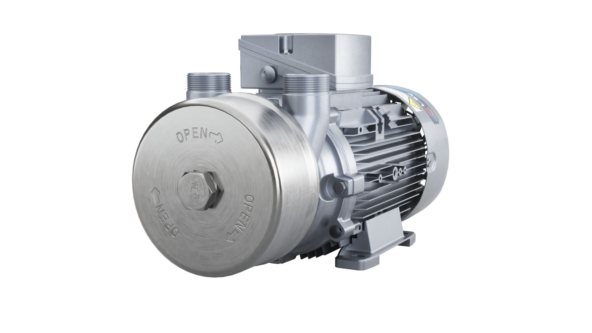
Elmo Rietschle 2BV7060
Elmo Rietschle 2BV7060 — Liquid Ring Vacuum Pumps with Max inlet pressure 200 kPa, Motor power 1.3 kW.
The 2BV7060 is a liquid-ring vacuum pump/compressor with an eccentrically arranged impeller in a cylindrical housing, driven by a 1.3 kW (50 Hz) or 1.6 kW (60 Hz) AC motor. As the smallest frame in the L-BV7N series, it is distinguished by a maximum inlet pressure of 2.0/2.4 bar abs. in compressor duty, versus 1.9 bar for the 2BV7061 and 8 bar for the 2BV7070/7071. It serves self-priming or operating-liquid-fed vacuum generation and low-pressure compression in process systems.
Elmo Rietschle L-BV7 Series — Model Comparison & Selection
Full specifications
| Max inlet pressure | 2 bar (50 Hz) 60 Hz: 2.4 bar |
| Motor power | 1.30 kW (50 Hz) 60 Hz: 1.60 kW |
| Operating principle | Liquid ring |
| Weight | 20 kg (2BV7060-2) 2BV7060-3: 25 kg |
| Weight (alt 2BV7060-2) mfr | 44 lb (2BV7060-2) |
| Weight (alt 2BV7060-3) mfr | 55 lb (2BV7060-3) |
| Power supply | AC (3~ 50/60 Hz) |
| Noise level | 70 dB (50 Hz) 60 Hz: 70 dB |
| Operating temperature | 80 °C |
| Protection rating | IP55 |
| Ambient temperature limit | 40 °C |
Description
Construction and series positioning
- Liquid-ring principle: an eccentrically mounted impeller rotates in a cylindrical housing; the operating liquid forms a rotating ring that draws gas through the inlet port, compresses it, and discharges it through the discharge port.
- The 2BV7060 is the smallest frame in the L-BV7N series. Sibling 2BV7061 offers 1.9 bar abs. max inlet pressure with a 2.5 kW motor; 2BV7070/7071 extend to 8 bar abs. and up to 6.3 kW. The 2BV7060 is therefore the low-pressure compressor / vacuum pump choice when discharge pressure at p1 = 1 bar abs. does not exceed 2.0 bar abs. (50 Hz) or 2.4 bar abs. (60 Hz).
- Available as sizes -2 (20 kg) and -3 (25 kg), in cast iron (standard, RAL 9006) or stainless steel, with IE3 or NP motor variants and ATEX category 2G versions.
Behavior under load and media limits
- Maximum permissible inlet pressure in compressor duty is 2.0 bar abs. at 50 Hz and 2.4 bar abs. at 60 Hz. In vacuum-pump operation the discharge pressure must not exceed 1.3 bar abs., and when pumped gases are passed on, 1.1 bar abs.
- Pumped gas/vapor temperature is limited to +80 °C; operating liquid must remain between +5 °C and +80 °C (nominal +15 °C). Minimum inlet pressure depends on operating-liquid temperature.
- Nominal operating-liquid flow rate is 0.20 m³/h with dry air and water at 15 °C; priming fill quantity is 0.40 l.
Installation, connection and operation
- Two operating modes are defined: self-priming operation and operation with operating-liquid feed (manual or automatic). The mode determines filling and commissioning procedure.
- In self-priming mode, the inlet pipe must be evacuated to an absolute pressure of 900 mbar or lower (i.e., a vacuum of at least about 100 mbar below atmospheric) before switch-on, and the liquid level in the feed pipe/reservoir must be at the same level as the center of the unit shaft; during operation the reservoir level may not drop below approximately 1 m below shaft center.
- With operating-liquid feed, set pre-pressure pA in the feed pipe approximately 1 bar above inlet pressure pB.
- The unit is bolted via 4 x M8-6.8 feet; maintain 34 mm clearance from the fan guard to adjacent surfaces and keep vibration velocity below 4.5 mm/s. Maximum installation height is 1000 m above sea level.
Integration & Operating Notes
In vacuum-pump operation the maximum discharge pressure is 1.3 bar abs.; when pumped gases/vapors are passed on, the limit is 1.1 bar abs. Downstream equipment and piping must be sized so back-pressure cannot rise above these values, otherwise the liquid ring can be disrupted and the unit may overheat or suffer mechanical damage.
The fan guard must remain at least 34 mm from any adjacent surface to ensure heat dissipation. The supporting surface and foundation must keep total vibration velocity below 4.5 mm/s; exceeding this shortens service life and can damage the pump. Bolt the feet with 4 x M8-6.8 fasteners.
Tighten terminal plate screws to 0.8–1.2 Nm (M4) or 1.8–2.5 Nm (M5). Maintain at least 5.5 mm clearance between bare live parts and to ground for nominal voltages up to 690 V, and ensure no protruding wire strands. Supply deviations must stay within ±5 % voltage and ±2 % frequency without performance reduction.
Before switching on in self-priming mode, the inlet pipe must be evacuated to an absolute pressure of 900 mbar or lower (i.e., a vacuum of at least about 100 mbar below atmospheric), and the liquid level in the feed pipe/reservoir must be at the same level as the center of the unit shaft. During operation the reservoir level may not drop below approximately 1 m below shaft center. Pre-throttle on the inlet side to establish these conditions.
For operation with operating-liquid feed, set the pre-pressure pA in the feed pipe approximately 1 bar above the inlet pressure pB. The nominal operating-liquid flow rate is 0.20 m³/h with dry air and water at 15 °C; regulate the feed accordingly to avoid flooding or starvation of the liquid ring.
The operating instructions include a fault table listing symptoms, causes, remedies and the personnel responsible for each corrective action. Consult it before servicing; corrective work must be carried out by the designated personnel. No fixed maintenance interval is stated in the supplied digest.
Selection & Integration Q&A
Pick the 2BV7060 when compressor discharge pressure at p1 = 1 bar abs. stays within 2.0 bar abs. (50 Hz) or 2.4 bar abs. (60 Hz) and motor power of 1.3/1.6 kW is sufficient. Choose 2BV7061 when a slightly lower maximum inlet pressure (1.9 bar abs.) is acceptable and a 2.5 kW motor is available; choose 2BV7070/7071 for up to 8 bar abs. and higher flows.
Provide operating liquid at 0.20 m³/h nominal (dry air, water at 15 °C) and keep it between +5 °C and +80 °C. In feed mode, set feed pre-pressure about 1 bar above inlet pressure. Priming fill quantity is 0.40 l.
Bolt the feet with 4 x M8-6.8, keep 34 mm clearance from the fan guard to adjacent surfaces, and ensure vibration velocity does not exceed 4.5 mm/s. Ambient temperature must not exceed +40 °C, and installation height must not exceed 1000 m above sea level; higher altitudes require consultation with service.
The base unit includes the pump-motor unit only; operating liquid, feed piping/reservoir, and electrical supply cables are not included. Commissioning requires filling with 0.40 l of operating liquid, checking direction of rotation, and establishing either self-priming conditions (inlet pressure of 900 mbar abs. or lower) or a regulated feed line at pA ≈ pB + 1 bar.