
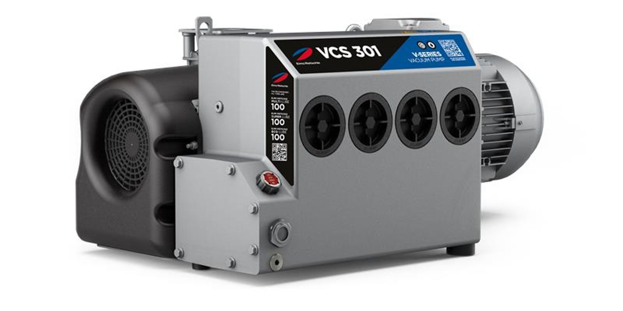
Elmo Rietschle V-VCS 100
Elmo Rietschle V-VCS 100 — Central Industrial & Medical Vacuum Systems.
The V-VCS 100 is a single-stage, oil-flooded rotary vane vacuum pump with integrated mesh filter, oil mist separator and non-return valve, rated at 100 m³/h at 50 Hz. Within the V-VCS series it is the standard model, distinguished from the V-VCX variant by lower water-vapour tolerance and from smaller/larger siblings by its 0.5–500 mbar(abs) continuous intake range. It serves as the vacuum source in central industrial vacuum systems, evacuating closed volumes up to 2% of its nominal capacity.
Elmo Rietschle V-VCS Series — Model Comparison & Selection
| Model | Motor power, kW | Noise level, dB | Pumping speed, m³/h | Ultimate pressure, mbar | Weight, kg | Current, A |
|---|---|---|---|---|---|---|
| V-VCS 100 Current | — | — | — | — | — | — |
| V-VCS 1100 | 25 | 81 | 26 | 1 | 807 | 42.9–74.5 |
| V-VCS 200 | — | — | — | — | — | — |
| V-VCS 40 | 1.1 | 63 | 48 | 0.5 | 39 | 2.34–4.07 |
| V-VCS 400 | 9 | 73 | 400 | 0.5 | 357 | 10.5–18.1 |
Full specifications
Description
Construction and series positioning
- Single-stage oil-flooded rotary vane design with coupling drive, integrated mesh filter, oil mist separator, non-return valve and adjustable gas ballast valve.
- The V-VCS 100 is the standard (non-VCX) variant; the V-VCX 100/150 offers increased water-vapour compatibility via glass-fibre reinforced epoxy slide gates, higher gas ballast quantity and higher oil sump temperature.
- Sibling models V-VCS 40, 200, 400 and 1100 cover smaller and larger nominal capacities; the V-VCS 100 sits between the 40 and 200 in displacement.
Behaviour under load and in different media
- Continuous intake pressure range: 0.5 to 500 mbar(abs). Operating outside this range risks oil leakage through the outlet.
- For continuous operation above 100 mbar(abs), the next higher motor output must be selected to avoid overheating.
- When evacuating closed systems, the connected volume must not exceed 2% of the nominal pumping capacity (100 m³/h at 50 Hz).
- Maximum permissible back pressure on the exhaust side is +100 mbar; no filter may be installed on the exhaust side.
- The integrated non-return valve maintains vacuum for approximately 2 minutes after pump stop; for longer hold times an external valve is required.
Installation, connection and operation
- Install horizontally with maximum inclination of 1° in all directions; secure against tipping.
- Maintain at least 30 cm clearance around cooling air inlets/outlets and 40 cm access space for maintenance (suction flange, oil fill, sight glass, drain, gas ballast, de-oiler).
- Motor: IP 55, insulation class F, per DIN EN 60034; permissible voltage deviation ±5%, frequency deviation ±2%.
- Use a motor protection switch with overload-dependent delayed trip (IEC 60947-4-1) to accommodate start-up current.
- For parallel operation of multiple pumps, install an external non-return valve in the suction line upstream of each pump.
- For standstill times >2 minutes, vent the suction line to atmospheric pressure (e.g. via a ball valve).
- Lubricating oil must be ISO VG 100 per DIN ISO 3448.
- Ambient and inlet temperature range: 12 to 40 °C; output reduction noticeable above 1000 m altitude.
- Storage: -10 to +60 °C, max 80% RH, dust-free, dry, vibration-free, protected from sun; for storage >3 months use preservation oil; do not store >6 months.
Integration & Operating Notes
Operating below 0.5 mbar(abs) or above 500 mbar(abs) can cause oil leakage through the outlet and invalidate pump performance. For continuous duty above 100 mbar(abs), specify the next higher motor output to prevent overheating.
When evacuating a closed system, the connected volume must not exceed 2% of the pump's nominal pumping capacity (100 m³/h at 50 Hz). Exceeding this ratio leads to excessive evacuation time and potential oil carry-over.
The machine must be installed on a plane, even floor and secured against tipping or falling. Greater inclination can impair oil distribution and cause premature wear or oil leakage.
Cooling air inlets and outlets must be at least 30 cm from adjacent walls to prevent recirculation of hot exhaust air. At least 40 cm space around the machine is required for access to the suction flange, oil filling point, oil sight glass, oil drain, gas ballast and de-oiler housing.
The motor is designed per DIN EN 60034 with IP 55 protection and insulation class F. Supply quality outside ±5% voltage or ±2% frequency deviation can cause loss of power or motor damage; verify the motor data plate matches the mains supply.
Select a motor protection switch with overload-dependent delayed switch-off (version with short-circuit and overload trigger per IEC 60947-4-1) to accommodate short-term excess current at start-up and avoid nuisance tripping.
Exhaust piping and any connected equipment must not create back pressure exceeding +100 mbar. No filter may be installed on the exhaust side, as it would increase back pressure and risk pump damage.
When operating multiple pumps in parallel, install an external non-return valve in the suction line upstream of each pump. This prevents a switched-off pump from being damaged by the suction capacity of operating pumps.
For standstill times longer than two minutes, vent the connected suction line to atmospheric pressure (e.g. via a ball valve) to avoid possible damage to the machine. The integrated non-return valve only maintains vacuum for approximately 2 minutes after stop.
Lubricating oil viscosity must comply with ISO VG 100 as per DIN ISO 3448. Incorrect viscosity can cause overheating, insufficient lubrication or poor vacuum performance. For storage longer than 3 months, use preservation oil instead of operating oil.
Operation outside this range requires consultation with the manufacturer. Ensure installation room ventilation and temperature control. Above 1000 m altitude, output reduction is noticeable; contact manufacturer for high-altitude installations.
Store dust-free, dry, vibration-free and protected from sun radiation at -10 to +60 °C and max 80% relative humidity. For long-term storage (>3 months), use preservation oil; do not store for more than 6 months.
Selection & Integration Q&A
Choose V-VCS 100 for standard vacuum duty with intake pressures 0.5–500 mbar(abs) and low water-vapour load. Select V-VCX 100 if the process carries higher water vapour (increased gas ballast, epoxy slide gates). Choose V-VCS 200 when nominal capacity above 100 m³/h at 50 Hz is required.
Suction line must be vented to atmosphere for standstill >2 min (e.g. ball valve). For parallel pumps, install an external non-return valve upstream of each pump. Exhaust back pressure must not exceed +100 mbar; no filter may be installed on the exhaust side.
Install horizontally with ≤1° inclination on a level floor, secured against tipping. Keep 30 cm clearance around cooling air inlets/outlets and 40 cm access space for maintenance. Ambient and inlet temperature must be 12–40 °C; above 1000 m altitude output reduction occurs.
Use only ISO VG 100 lubricating oil per DIN ISO 3448; for storage >3 months use preservation oil. Maintenance includes oil changes, oil separator elements, fan, motor and coupling checks per the maintenance table. External non-return valves, vent valves and motor protection switch are not included and must be provided by the installer.