
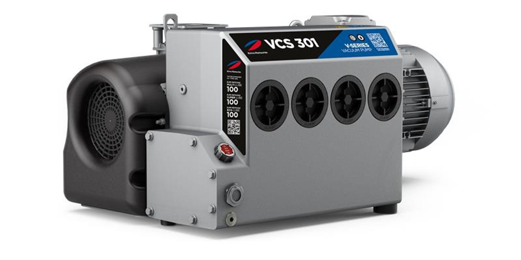
Elmo Rietschle V-VCS 40
Elmo Rietschle V-VCS 40 — Central Industrial & Medical Vacuum Systems with Motor power 1.1 kW, Noise level 66 dB, Pumping speed 40 m³/h.
Single-stage oil-flooded rotary vane vacuum pump V-VCS 40 with G 1 1/4 suction connection, 40 m³/h at 50 Hz and 0.5 mbar ultimate vacuum. As the smallest standard V-VCS size it differs from the V-VCX 40 by its standard gas ballast and non-reinforced slide gates, suiting dry-gas duty. It serves fine-vacuum evacuation and continuous holding in central vacuum systems.
Elmo Rietschle V-VCS Series — Model Comparison & Selection
| Model | Motor power, kW | Noise level, dB | Pumping speed, m³/h | Ultimate pressure, mbar | Weight, kg | Current, A |
|---|---|---|---|---|---|---|
| V-VCS 40 Current | 1.1 | 63 | 48 | 0.5 | 39 | 2.34–4.07 |
| V-VCS 100 | — | — | — | — | — | — |
| V-VCS 1100 | 25 | 81 | 26 | 1 | 807 | 42.9–74.5 |
| V-VCS 200 | — | — | — | — | — | — |
| V-VCS 400 | 9 | 73 | 400 | 0.5 | 357 | 10.5–18.1 |
Full specifications
| Motor power | 1.1 kW (50 Hz) |
| Noise level | 63 dB (50 Hz) 60 Hz: 66 dB |
| Pumping speed | 40 m³/hour (50 Hz) 60 Hz: 48 m³/hour |
| Ultimate pressure | 0.5 mbar |
| Rotational speed | 1455 rpm (50 Hz) |
| Nominal suction capacity mfr | 40 m3/h (50 Hz) |
| Nominal suction capacity mfr | 48 m3/h (60 Hz) |
| Vacuum connection mfr | G 1 1/4 |
| Motor version mfr | GB IE3 |
| Motor note mfr | UL (UR), CSA, EAC (GB IE3) |
| Weight | 39 kg |
| Length | 598 mm |
| Max. weight without motor mfr | 39 kg |
| Motor weight mfr | 18.0 kg (GB IE3) |
| Current | 4.07 / 2.34 A (50 Hz) |
| Voltage | 230 / 400 V (50 Hz) |
| Motor voltage (version GB, IE3) mfr | 230 / 400 V ±10 % (50 Hz) |
| Motor speed (version GB, IE3) mfr | 1455 min-1 (50 Hz) |
| Motor current (version GB, IE3) mfr | 4.07 / 2.34 A (50 Hz) |
| Motor weight (version GB, IE3) mfr | 18.0 kg |
| Motor total length a* (version GB, IE3) mfr | 598 mm |
| Motor power (version GC, IE3) mfr | 1.25 kW (50 Hz) |
| Motor voltage (version GC, IE3) mfr | 230 / 400 V ±10 % (50 Hz) |
| Motor speed (version GC, IE3) mfr | 1455 min-1 (50 Hz) |
| Motor current (version GC, IE3) mfr | 4.77 / 2.74 A (50 Hz) |
| Motor power (version GC, IE3) mfr | 1.5 kW (60 Hz) |
| Motor voltage (version GC, IE3) mfr | 265 / 460 V ±10 % (60 Hz) |
| Motor speed (version GC, IE3) mfr | 1755 min-1 (60 Hz) |
| Motor current (version GC, IE3) mfr | 4.84 / 2.79 A (60 Hz) |
| Motor weight (version GC, IE3) mfr | 23.0 kg |
| Motor total length a* (version GC, IE3) mfr | 598 mm |
| Motor remark (version GB/GC, IE3) mfr | UL (UR), CSA, EAC |
| Motor remark (version GC, IE3) mfr | UL (UR), CSA, CC-Nr., EAC |
| Oil capacity mfr | 3.0 l |
| Average noise level mfr | 66 dB(A) (60 Hz) |
| Ultimate vacuum (standard) mfr | 0.5 mbar (abs.) |
| Average noise level (EN ISO 3744) mfr | 63 dB(A) (50 Hz) |
| Average noise level (EN ISO 3744) mfr | 66 dB(A) (60 Hz) |
| Ultimate vacuum (standard) mfr | 0.5 mbar (abs.) (standard version) |
| Ultimate vacuum (standard) mfr | 3.0 mbar (abs.) (V-VCX version) |
Description
Construction and series position
- Single-stage oil-flooded rotary vane pump: eccentric rotor with slide gates divides the housing; oil seals the gap, lubricates and removes compression heat.
- Integrated suction mesh filter, oil-mist separator with oil return, fan and oil cooler, non-return valve, and standard gas ballast valve.
- Within the V-VCS/VCX 40/50/75 family, the V-VCS 40 is the smallest standard model; the V-VCX 40 is the water-vapour/solvent variant with glass-fibre reinforced epoxy slide gates, larger gas ballast and higher oil sump temperature. Larger V-VCS 50/75 and the separate V-VCS 100–1300 range cover higher flows.
- Vacuum connection G 1 1/4; max. weight without motor 39 kg; oil capacity 3.0 l.
Behaviour under load and in different media
- Continuous intake pressure range 0.5–500 mbar (abs.) for the V-VCS; operation outside this range risks oil leaking through the outlet.
- Nominal suction capacity 40 m³/h at 50 Hz, 48 m³/h at 60 Hz; ultimate vacuum 0.5 mbar (abs.).
- For continuous operation above 100 mbar (abs.) the next higher motor output should be selected.
- When evacuating closed systems, the volume to be evacuated must not exceed 2% of nominal pumping capacity.
- Standard gas ballast prevents condensation of small water-vapour quantities at operating temperature; for humid gases or solvents the V-VCX variant is the intended choice.
- Average noise 63 dB(A) at 50 Hz, 66 dB(A) at 60 Hz (EN ISO 3744).
Drive, installation and operation
- Flanged three-phase motor, versions GB (1.1 kW, 1455 min⁻¹, 4.07/2.34 A at 230/400 V, 50 Hz) or GC (1.25 kW at 50 Hz, 1.5 kW at 60 Hz; 4.77/2.74 A at 230/400 V, 50 Hz; 4.84/2.79 A at 265/460 V, 60 Hz; 1455 min⁻¹ at 50 Hz, 1755 min⁻¹ at 60 Hz); IP 55, insulation class F, DIN EN 60034; UL (UR), CSA, EAC marked.
- Electrical installation to EN 60204 by a qualified electrician; main switch and motor protection switch supplied by the operator.
- Install horizontally (max. 1° inclination), secured against tipping, with ≥30 cm clearance at cooling air inlets/outlets and ≥40 cm around the machine for maintenance.
- Suction and exhaust pipes screwed in by hand; flexible connections recommended; exhaust must not be restricted, no exhaust filter, back pressure ≤ +100 mbar.
- For standstill >2 minutes vent the suction line to atmosphere; for parallel operation fit an external non-return valve upstream of each pump.
- Ambient and inlet temperature 12–40 °C; output reduction above 1000 m above sea level.
Integration & Operating Notes
Operating the V-VCS 40 continuously outside its intake pressure range causes oil to be carried out through the outlet opening. Size the process window and any bypass control so the pump does not run continuously beyond these limits; for sustained operation above 100 mbar (abs.) specify the next higher motor output.
When evacuating a closed volume, the volume to be evacuated must be no more than 2% of the nominal pumping capacity (about 0.8 m³ for the 40 m³/h rating). Larger recipients require a bigger pump or a staged evacuation strategy to avoid prolonged operation outside the permissible range.
The pump must sit on a plane, load-bearing floor with maximum inclination 1° in all directions and be secured against tipping or falling. Keep cooling air inlets and outlets at least 30 cm from walls and leave at least 40 cm around the machine so filters, oil sight glass, oil drain and gas ballast remain accessible.
No filter may be installed on the exhaust side and the exhaust opening must not be closed or restricted; permissible back pressure is +100 mbar. Size exhaust lines accordingly, otherwise the oil-mist separation and cooling behaviour degrade and the pump may overheat.
The integrated non-return valve holds the evacuated system for only about 2 minutes after stop. Provide an air-release position such as a ball valve in the suction line and sequence it to vent to atmospheric pressure for longer standstill; in parallel operation add an external non-return valve upstream of each pump.
The motor tolerates only ±5% voltage and ±2% frequency deviation from its data plate unless stated otherwise. The operator must provide the main switch and a motor protection switch, and electrical installation must follow EN 60204 by a qualified electrician; the machine has no built-in emergency stop, so integrate it into the plant safety circuit.
Lubricating oil must comply with ISO VG 100 (DIN ISO 3448); a dark colour from graphite leaching after first filling is normal. Check the oil level at the sight glass during operation and top up to the upper edge. Maintenance also covers the suction mesh filter, gas ballast filter disc, oil separator elements, motor and coupling per the maintenance table.
Operation outside 12–40 °C requires consultation with the manufacturer; ensure the installation room is ventilated because extracted air carries a small oil-aerosol residue. Above 1000 m altitude output reduction is noticeable, and frequent switching around 10 times per hour or high inlet temperatures require manufacturer consultation.
Selection & Integration Q&A
Pick the V-VCS 40 for dry gases and fine vacuum down to 0.5 mbar at 40 m³/h. Choose the V-VCX 40 for humid gases or solvents (reinforced slide gates, larger gas ballast, higher oil sump temperature). Move to V-VCS 50/75 only when the 40 m³/h capacity is insufficient.
Suction G 1 1/4 piped by hand with a flexible connection and an air-release valve for standstill over 2 min; exhaust unrestricted, no filter, back pressure ≤ +100 mbar. Panel needs a main switch and motor protection switch to EN 60204, mains within ±5% voltage and ±2% frequency.
Horizontal within 1°, secured against tipping, ≥30 cm at cooling air inlets/outlets and ≥40 cm around the machine. Ambient/inlet 12–40 °C, altitude ≤1000 m without derating, and switching about 10 times per hour or high inlet temperatures require manufacturer consultation.
ISO VG 100 lubricating oil (3.0 l sump), suction mesh filter, gas ballast filter disc and oil separator elements are service items; the main switch, motor protection switch and suction-line vent valve are not included. Follow the maintenance table in BA 238-EN; repairs only with original spare parts (E 233).