
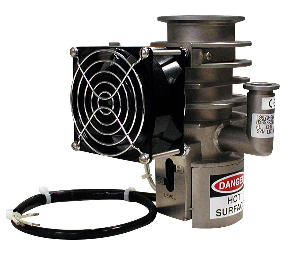
Agilent Technologies AX 65 Diffusion Pump
Agilent Technologies AX 65 Diffusion Pump — Liquid chromatography.
The AX-65 is a three-stage, self-aligning aluminum jet diffusion pump with a stainless-steel body, supplied in KF50 (NW50) or ISO63 inlet variants and 200 W or 250 W heater configurations. It delivers 65 l/s air pumping speed with 0.30 Torr·l/s maximum throughput and requires a 1.5 cfm backing pump. It is used to generate high vacuum in analytical and laboratory systems, including leak detectors.
Full specifications
| Pumping speed | 65 Air |
| Cooldown Time | 10 minutes |
| Electrical power | 200 Watts |
| Operating range | 3 Torr |
| Pumping Speed, Maximum (air) | 65 l/s |
| Santovac 5 | 40 cc |
| Throughput (Air), Max. Optimum Range mfr | Torr-l/s l/s |
| Throughput (Air), Max. Overload Range (@ 1x10⁻² Torr) mfr | 0.40 l/s |
| Forepressure, Max. No Load mfr | Torr Torr |
| Forepressure, Max. Full Load mfr | 0.78 mbar |
| Compression Ratio Air mfr | 4 |
| Compression Ratio He mfr | 2 |
| Backstreaming Rate at Pump Inlet mfr | 2 min |
| Warmup Time mfr | utes utes |
| Recommended backing pump capacity mfr | cfm cfm |
| Body mfr | Stainless steel steel |
| Jet Assembly mfr | Three-stage, self-aligning, aluminum, w/aluminum |
| Installation mfr | 2 |
| Compression Ratio (Air) mfr | 4 |
| Compression Ratio (He) mfr | 2 |
| Poor system pressure mfr | Leaks in system, virtual or real real |
| Poor ultimate pressure mfr | Contaminated pump fluid fluid |
| Low speed (Prolonged cycle after checking gas load conditions) mfr | Low heat input input |
| Inlet pressure surges mfr | Incorrect heater voltage voltage |
| Pump will not start mfr | Safety circuits open open |
| Overload Range (@ 1x10⁻² Torr) mfr | Torr-l/s l/s |
| Full Load mfr | Torr Torr |
| AX-65 with internal baffle mfr | 165 |
| NEOVAC SY mfr | 5 liters |
| DC-702 Silicone mfr | 5 liters |
| DC-704 Silicone mfr | 5 liters |
| DC-705 Silicone mfr | 1 liters |
| Fax: 1 781 860 9252 mfr | please visit our website for individual office i |
| Loss of utility: water and/or electricity mfr | Provide sufficient backup water and power supply |
| Loss of electrical ground integrity mfr | Incorporate ground fault interrupt circuit into |
| Positive pressure in pumping system mfr | Integrate pressure relief valve in vacuum system |
| Explosion mfr | Integrate pressure relief valves Do not use hydr |
| Do not run pump without proper backing or holding pump mfr | Overpressure Overpressure |
| Do not run pump when not evacuated below 0.5 Torr (0.66 mbar) mfr | Overpressure Overpressure |
| Do not admit air to, or rough through, a pump with hot boiler mfr | Overpressure plus strong oxidizer oxidizer |
| Do not contaminate pump with explosive vapors mfr | Lower explosive threshold of gas mixtures mixtur |
| Maximum throughput mfr | 0.30 liters/sec |
| Forepressure limit mfr | 0.5 Torr |
| Fan clearance mfr | 1 inch |
| Weight | 8 lbs |
| Voltage mfr | 165 |
| High voltage mfr | Prevent personnel contact with high voltages; de |
| Fuse rating mfr | 240 A |
| Inlet flange | 50 N/A |
| Do not open drain or fill plug while pump is under vacuum, especially when it is hot mfr | Overpressure plus strong oxidizer oxidizer |
| Fluid Charge mfr | cc cc |
| High chamber contamination of the pump fluid mfr | Forepressure too high high |
| Do not run pump with low level of pump fluid mfr | Overtemperature Overtemperature |
| Do not machine or weld any part of the pump without removing all fluid or solvent residue in pump mfr | Source of ignition ignition |
| Do not use unsuitable pumping fluid mfr | Lower explosive threshold of gas mixture mixture |
| Fluid charge for empty pump mfr | 30 |
| Ambient temperature limit | 5 °C |
| Cooling Fan mfr | cfm cfm |
| Maximum relative humidity mfr | 80 |
| Do not run pump without cooling water mfr | Overtemperature Overtemperature |
| AX-65 with standard cold cap mfr | 165 |
Description
Construction and series positioning
The AX-65 is a single-model diffusion pump line; no sibling models are listed. Within the line, configurations differ by inlet flange (KF50/NW50 or ISO63), cold-cap type (standard cold cap or internal baffle), and heater/voltage (115 V 250 W, 220 V 250 W, 115 V 200 W, 220 V 200 W, 90 V 250 W, 165 V 250 W; 50/60 Hz, 1 phase, ±10%). The body is stainless steel; the jet assembly is three-stage, self-aligning aluminum with an aluminum cold cap. The pump weighs 8 lbs and carries a 30 cc fluid charge.
Behavior under load
Air throughput is 0.19 Torr·l/s in the optimum range and 0.30 Torr·l/s in the overload range at 1×10⁻² Torr. Maximum forepressure is 0.75 Torr at no load and 0.60 Torr at full load; the manual requires foreline pressure to stay below approximately 0.5 Torr during operation. Compression ratio is 4 for air and 2 for helium. Warmup takes 7 minutes and cooldown 10 minutes. Backstreaming rate at the pump inlet is 2 (unit as printed).
Installation, control and operation
The pump must be mounted vertical and plumb with the inlet flange horizontal within ±1°. The inlet uses an O-ring and centering ring with NW50 clamp; the foreline is NW16. The cooling fan requires at least 1 inch clearance from the closet surface and is mounted 90° from the foreline. Heater wiring: green wire to ground, the other two to line voltage. Fan wiring is selected for 115 VAC or 230 VAC by pairing leads as described in the manual. Supplementary fusing must not exceed 240 V, 15 A, fast acting. A normally-closed thermal switch opens on loss of cooling, high pressure, or low fluid level and resets automatically; an optional normally-open Pump Ready switch closes at operating temperature. Before starting the heater, rough pumping must reduce gas load to 0.30 Torr·l/s or less. If heater and fan are wired separately, run the fan about 10 minutes after heater off; if wired together, allow about 30 minutes cooldown before venting, and confirm the body just above the boilerplate is at most 130 °F before venting.
Integration & Operating Notes
Mount the pump body vertical and plumb; a tilted inlet causes uneven fluid level and boiler-plate overheating. Provide at least 1 inch clearance between the cooling fan and the closet surface, with the fan 90° from the foreline.
Install fast-acting overcurrent protection rated no larger than 240 V, 15 A in the supply to the heater. Wire the green heater lead to ground and the remaining two to line voltage; select fan lead pairing for 115 VAC or 230 VAC to match the supply.
Start the heater only after rough pumping has reduced the gas load to the maximum throughput specification of 0.30 Torr·l/s or less. During operation keep foreline pressure below approximately 0.5 Torr; above this the pump will not function properly and backstreaming increases.
The normally-closed overtemperature switch on the pump body opens on loss of cooling, high pressure, or low fluid level and resets automatically after the condition is corrected. An optional normally-open Pump Ready switch closes at operating temperature for use in startup sequencing.
If heater and fan are wired separately, run the fan about 10 minutes after heater off; if wired together, allow about 30 minutes cooldown. Confirm the body just above the boilerplate is at most 130 °F before admitting air. Clean with acetone then isopropyl alcohol and dry with dry nitrogen; do not use solvents on O-rings.
Selection & Integration Q&A
Choose 250 W when using polyphenyl ether (Santovac 5), which is required for leak-detector service. Choose 200 W with a lower-boiling fluid such as DC-704. Inlet flange (KF50/NW50 or ISO63) and cold cap versus internal baffle are separate choices.
A backing pump of 1.5 cfm (2.5 m³/hr) capacity connected to the NW16 foreline. The backing pump must hold foreline pressure below approximately 0.5 Torr during operation; maximum forepressure is 0.75 Torr no load and 0.60 Torr full load.
Plan for 30 cc fluid charges (Santovac 5 or DC-704 per heater power), inlet O-ring and NW50 centering ring, NW16 foreline hardware, and fast-acting fusing ≤240 V, 15 A. Replacement parts include jet assembly, cold cap, inlet baffle, heater harnesses by voltage/power, fan and foreline baffle.