
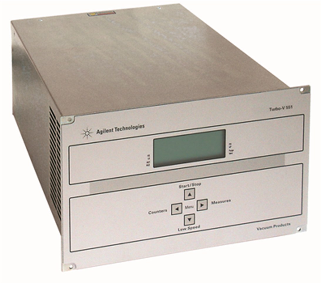
Agilent Technologies Turbo V 551
Agilent Technologies Turbo V 551 — Turbomolecular Vacuum Pumps.
The Turbo-V 551 is a rack-mount turbomolecular pump controller (rear-panel example X3501-64001) for Turbo-V 551 pumps, powered from a 3-conductor earthed mains cable and operated from the front panel or RS-232/RS-485. It is distinguished within the series by its integrated power module, logic I/O with programmable analog output, and vent/drain and external-fan outputs. It sequences pump start/stop, enforces the J1 interlock, and reports pump and controller status over serial windows.
Direct drop-in replacements
Full specifications
| Stop speed reading default mfr | 1 |
| Output for pump: Power during pump ramp-up mfr | 430 maximum |
| Power normal (pump water cooled) mfr | 350 maximum |
| Power normal (pump air cooled) mfr | 220 maximum |
| Power cable mfr | 3 long |
| Pump cable mfr | 5 cable |
| Protection category mfr | 20 |
| Installation category mfr | II II |
| Turbo-V vent mfr | 3501 |
| CHECK CONNECTION TO PUMP mfr | Wrong connection between the pump and the contro |
| FAULT: TOO HIGH LOAD mfr | In normal operation, the current drawn by the pu |
| FAULT: SHORT CIRCUIT mfr | During normal functioning , a short-circuit cond |
| controlled venting deceleration range mfr | 3 Hz/s |
| Pump Bearing Overtemperature Trip | 60 °C |
| Weight (both models) mfr | 6.3 kg |
| Frequency | 50...60 Hz |
| Power consumption | 800 maximum |
| Cooling fan control voltage mfr | 24 Vdc |
| Input: Voltage mfr | 100 phase |
| Fuse: Mains mfr | 2 fuses |
| Controller Transformer Overtemperature Trip | 65 °C |
| Serial communication (T-Plus kit) mfr | 232 software |
| Turbo-V 551 Rack Controller mfr | 3501 |
| T-Plus communication software and serial cable kit mfr | 9699883 |
| Mains cable NEMA plug 3m long mfr | 9699958 |
| Mains cable European plug 3m long mfr | 9699957 |
| maximum serial/I/O cable length mfr | 30 m |
| Max Altitude | 2000 m |
| Operating temperature | 5 °C |
| Storage temperature | -20 °C |
| Pollution degree mfr | 2 |
| Turbo-V HT Rack Air Cooling kit mfr | 3501 |
Description
Construction and positioning
- Rack-mount controller for Turbo-V 551 turbomolecular pumps; rear-panel example model X3501-64001.
- Rear panel carries the power module with fuses, mains socket and EMC filter; RS-232/RS-485 port; logic I/O connector with programmable analog output and interlock jumper; pump cable; vent/drain valve output; external fan output.
- No sibling models are listed in the verified facts, so positioning is limited to the controller's own configuration: it is the rack controller variant, not a bench-only or pump-integrated drive.
Behavior and status reporting
- Start is initiated from the front-panel START button; stop from STOP. The safety interlock connector must be fitted to J1 before the pump can run.
- Serial windows expose pump current, 3-phase voltage, output power, driving frequency, bearing temperature, system status, error code, controller internal temperature, body pump temperature and rotational frequency (windows 200–232).
- System status window 205 codes: Stop=0, Waiting intlk=1, Ramp-Up=2, Auto-tuning=3, Braking=4, Normal=5, Fail=6.
- Window 167 (Stop Speed Reading) defaults to 1 (Yes), so rotation speed is also measured in Braking status; set to 0 to disable.
- Cycle time, cycle number and pump life counters (windows 300–302) range 0–999999 and are zeroed by the reset command.
Installation, control and operation
- Indoor use only; bench or rack installation with free cooling-air circulation. Ambient 0 °C to +45 °C, relative humidity 0–95 % non-condensing. Do not install in rain, snow, ice, steam, aggressive gases, or explosive/flammable atmospheres.
- Powered from a 3-conductor mains cable with internationally approved plug into a properly earthed socket; disconnect mains before installation or maintenance.
- Setup menu is entered by pressing buttons 2 and 3 together for at least 2 seconds; all four front-panel buttons then navigate menus and edit values.
- The controller is maintenance-free; any intervention must be by authorized personnel. Agilent repair or advanced exchange service provides replacement controllers.
Integration & Operating Notes
The controller will not start the pump unless a short circuit is present between J1 pins 3–9 and pins 4–15, or an external interlock is closed. Without it the system status reads Waiting intlk=1 and the pump remains stopped; the supplied interlock connector/jumper must be fitted to J1.
The controller must be powered from a 3-conductor mains cable with an internationally approved plug connected to a properly earthed socket. This is required to avoid electric shock and meet CE requirements; disconnect mains before installation or maintenance.
Bench or rack installation is permitted only if cooling air can circulate freely around the unit. Indoor use only; avoid rain, snow, ice, steam, aggressive gases, and explosive/flammable atmospheres. Relative humidity must stay 0–95 % non-condensing.
Pump top bearing overtemperature faults above 60 °C and controller transformer overtemperature faults above 65 °C. Provide adequate pump and controller cooling; after cooldown, press START twice to restart, since a single START press is not sufficient for fault reset.
The FAULT: TOO HIGH LOAD remedy includes checking that the pump cable length is correctly set. An incorrect pump cable length configuration can cause false overcurrent/load faults; verify the configured length against the installed cable.
The cycle time, cycle number and pump life counters (windows 300–302) range 0 to 999999 and are all zeroed by the reset command. Plan maintenance tracking accordingly, since resetting erases the accumulated counters.
The rear-panel external fan output connector supplies 24 Vdc control for the pump cooling fan. Account for this when wiring cabinet cooling or external fan hardware.
Selection & Integration Q&A
Choose the rack controller when the drive must sit in a rack or on a bench with its own power module, RS-232/RS-485 port, logic I/O with programmable analog output, and vent/drain and external-fan outputs. No sibling models are listed in the verified facts, so confirm alternative variants against Agilent documentation before specifying.
A 3-conductor earthed mains supply with approved plug, the J1 interlock short between pins 3–9 and 4–15 (or a closed external interlock), and the pump cable with its length correctly configured. RS-232/RS-485 and the logic I/O analog output are available for remote monitoring and sequencing.
Indoor bench or rack installation only, with free cooling-air circulation; ambient 0 °C to +45 °C and 0–95 % relative humidity non-condensing. Avoid rain, snow, ice, steam, aggressive gases and explosive/flammable atmospheres. Overtemperature trips at 60 °C bearing and 65 °C transformer require cooldown and a double START press to restart.
The controller is maintenance-free; any intervention must be by authorized personnel, and Agilent repair or advanced exchange service provides a replacement controller. The interlock jumper is supplied with the mating connector; mains cable, pump cable, external fan and vent/drain valve hardware are separate items to be specified. Persistent OVERVOLTAGE after restart requires Agilent service.