
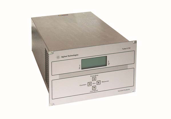
Agilent Technologies Turbo V 701
Agilent Technologies Turbo V 701 — Turbomolecular Vacuum Pumps.
The Turbo V 701 is a rack-mount turbomolecular pump controller (rear-panel variant X3501-64002) driving the Turbo-V 701 pump through a dedicated pump cable. It manages start/stop, braking and auto-tuning, with overtemperature trips at 60 °C pump bearing and 65 °C controller transformer. It is the power, interlock and serial-diagnostics interface between the pump and the vacuum system.
Direct drop-in replacements
Full specifications
| Output power | expressed in W |
| Stop speed reading default mfr | 1 |
| Error code mfr | Bit description: see the following figure figure |
| Output for pump: Power during pump ramp-up mfr | 430 maximum |
| Power normal (pump water cooled) mfr | 350 maximum |
| Power normal (pump air cooled) mfr | 250 maximum |
| Power cable mfr | 3 long |
| Pump cable mfr | 5 cable |
| Protection category mfr | 20 |
| Installation category mfr | II II |
| Turbo-V vent mfr | 3501 |
| CHECK CONNECTION TO PUMP mfr | Wrong connection between the pump and the contro |
| Controlled venting deceleration range mfr | 3 Hz/s |
| Pump Bearing Overtemperature Trip | 60 °C |
| Pump bearing temperature mfr | expressed in °C °C |
| Weight (both models) mfr | 6.3 kg |
| Frequency | 50...60 Hz |
| Power consumption | 800 maximum |
| Cooling fan control voltage mfr | 24 Vdc |
| Pump current mfr | expressed in mA dc mA dc dc |
| 3 phase voltage mfr | expressed in Vrms Vrms |
| Driving frequency mfr | expressed in Hz Hz |
| Rotational frequency mfr | in Hz Hz |
| Input: Voltage mfr | 100 phase |
| Fuse: Mains mfr | 2 fuses |
| Controller Transformer Overtemperature Trip | 65 °C |
| Controller Internal temperature mfr | in °C °C |
| Serial communication (T-Plus kit) mfr | 232 software |
| Turbo-V 701 Rack Controller mfr | 3501 |
| T-Plus communication software and serial cable kit mfr | 969 |
| Mains cable NEMA plug 3m long mfr | 969 |
| Mains cable European plug 3m long mfr | 969 |
| Maximum serial/I/O cable length mfr | 30 m |
| Max Altitude | 2000 m |
| Operating temperature | 5 °C |
| Storage temperature | -20 °C |
| Body pump temperature mfr | in °C °C |
| Pollution degree mfr | 2 |
| Turbo-V HT Rack Air Cooling kit mfr | 3501 |
Description
Architecture and positioning
- Rack or bench controller dedicated to the Turbo-V 701 pump; rear panel carries the fused power module with mains socket and EMC filter, the pump cable, RS-232/RS-485 port, J1 logic I/O with programmable analog output, vent/purge valve outputs and a 24 Vdc external-fan output.
- No sibling variants are listed in the verified facts, so selection is against the pump/controller pairing itself rather than a family of controller sizes.
Behavior under load and in different states
- The controller sequences through Stop (0), Waiting interlock (1), Ramp-Up (2), Auto-tuning (3), Braking (4), Normal (5) and Fail (6), reported in status window 205; rotational frequency, pump current, 3-phase voltage, output power, driving frequency and bearing temperature are readable in windows 200–204 and 232.
- Protection is layered: pump current above the programmed value raises TOO HIGH LOAD; power-circuit short circuit is detected after the start phase; overvoltage points to the supply section or a mains disturbance; bearing above 60 °C and transformer above 65 °C each force a fault.
- Stop-speed reading is enabled by default (window 167 = 1), so speed is measured during braking as well; set to 0 if that is not wanted.
Installation, control and operation
- Indoor use only, 0 °C to +45 °C ambient, 0–95 % RH non-condensing, with free cooling-air circulation around the unit; not for rain, snow, ice, dust, aggressive gases or explosive atmospheres.
- Mains must be a 3-conductor cable with approved plug into an earthed socket. START/STOP are front-panel pushbuttons; holding buttons 2 and 3 for at least 2 seconds opens the setup menu, navigable with all four buttons, so configuration is possible without serial link.
- Cycle time, cycle number and pump life (windows 300–302, 0–999999) are zeroed by the reset command.
Integration & Operating Notes
The supplied mating connector with its interlock jumper must be seated on J1 before START is accepted; otherwise the controller stays in PUMP WAITING INTERLOCK. The interlock is active when the short between pins 3–9 and 4–15 of P1 is interrupted or an external interlock opens, so any door switch or gauge relay must be wired to close that loop.
Exceeding either threshold trips FAULT: PUMP OVERTEMP or FAULT: CONTROLLER OVERTEMPERATURE and stops the pump. Provide the external fan on the 24 Vdc fan output and keep rack airflow free; after cooling, START must be pressed twice to restart, so automatic restart logic in the host controller must account for the double press.
The controller must be fed from a 3-conductor mains cable with an internationally approved plug into a properly earthed socket; this is both a shock-hazard and CE-compliance requirement. Overvoltage faults are attributed to the supply section or mains disturbances, so the feed should be free of switching transients before blaming the controller.
TOO HIGH LOAD is raised when pump current exceeds the programmed value during normal operation; the manual directs checking that the rotor turns freely and that the correct pump cable length has been set. Cable length is therefore a configuration parameter, not just wiring, and must match the installed pump cable.
The rack controller is maintenance-free and any intervention must be by authorized personnel; failures are handled through Agilent repair or advanced exchange rather than on-site repair. Record windows 300–302 (cycle time, cycle number, pump life) before any reset, because the reset command zeroes these counters and erases the lifetime history.
Install on a bench or in a suitable rack only where cooling air can circulate freely, within 0 °C to +45 °C and 0–95 % RH non-condensing. Rain, snow, ice, dust, aggressive gases and explosive or fire-hazardous atmospheres are excluded, which rules out many rough-vacuum foreline rooms unless the controller is placed outside them.
Selection & Integration Q&A
Choose the rack controller (rear-panel variant X3501-64002) when the Turbo-V 701 pump is to be driven from a bench or 19-inch rack with front-panel START/STOP, J1 logic I/O, RS-232/RS-485 and dedicated vent/purge and 24 Vdc fan outputs. No sibling controller variants are documented in the verified facts, so confirm the pump/controller pairing and cable length rather than selecting between controller sizes.
An earthed 3-conductor mains feed with approved plug; the supplied J1 mating connector with interlock jumper (or an external interlock closing pins 3–9 and 4–15 of P1); the correct pump cable with its length configured; and wiring for the 24 Vdc cooling fan plus vent and purge valves on the dedicated rear-panel outputs. Serial host connects via RS-232/RS-485.
The controller is maintenance-free; interventions are by authorized personnel only, with Agilent repair or advanced exchange as the failure path. The J1 mating connector with interlock jumper is supplied, but the mains cable, pump cable, external fan, vent and purge valves and serial cabling are system-side items. Record windows 300–302 before any reset, which zeroes cycle time, cycle number and pump life.