BINDER VDL 56
BINDER VDL 56 — Drying ovens with Temperature 9…110 °C.
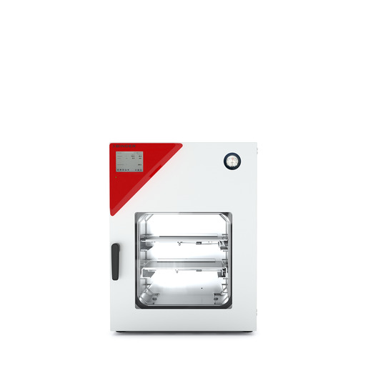
The BINDER VDL 56 is a 55-litre vacuum drying chamber with a microprocessor program controller MB2, built for drying flammable solvents under reduced pressure. It operates from +9 °C above ambient to 110 °C and is distinguished within the VDL series by its mid-size 55 L interior, between the 23 L and 115 L siblings. It serves as the solvent-safe drying stage in laboratory and pilot processes requiring controlled vacuum, temperature and compressed-air flushing.
BINDER VDL Series — Model Comparison & Selection
Full specifications
| Temperature | 9...110 °C |
| Heating time to 100°C | 140 min |
| Interior volume | 55 L (VDL 56) |
| Leak rate | 0.01 bar/h |
| Load per rack | 20 kg (VDL 56) |
| Nominal power | 1.4 kW |
| Permitted load | 60 kg (VDL 56) |
| Pressure fluctuation over time | 1 mbar |
| Temperature fluctuation | 0.1 K |
| Temperature uniformity | 1.2 K |
| Rear wall clearance | 100 mm (VDL 56) |
| Side wall clearance | 70 mm (VDL 56) |
| Article Number mfr | 9630 |
| Pressure fluctuation over time at 400 mbar mfr | 70 mbar |
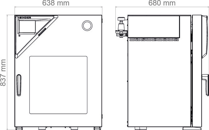
| Depth | 461 mm (VDL 56) |
| Height | 815 mm (VDL 56) |
| Width | 638 mm (VDL 56) |
| Power frequency | 50 Hz |
| Rated voltage | 200...230 V |
| Unit fuse | 8.0 A |
| Phase (Nominal voltage) mfr | 1 |
| Vacuum connection with small flange mfr | 16 mm |
Description
Construction and series positioning
- The VDL 56 is the 55 L member of the VDL vacuum drying oven series; siblings are the 23 L VDL 23 and the 115 L VDL 115, all rated to the same +9 °C above ambient to 110 °C working range.
- The chamber is built around a triangular instrument box housing the MB2 microprocessor program controller, with rear connections for vacuum, compressed air, inert gas and electrical supply.
- Two voltage variants exist: VDL056-230V (200...230 V, 1~, 50/60 Hz, CEE 7/7 plug) and VDL056-120V (100...120 V, 1~, 50/60 Hz, NEMA 5-15 plug). The matched electrical data for this card correspond to the 230 V variant.
- Interior dimensions are 638 mm wide, 815 mm high and 461 mm deep (net); nominal power is 1.4 kW and the unit fuse is 8.0 A.
Behaviour under load and in process media
- Heating from ambient to 100 °C takes 140 min. Temperature fluctuation is stated as 0.1 ± K, and pressure fluctuation over time as 1 ± mbar.
- The chamber will not heat until the internal pressure reaches the 100 mbar threshold; no heater release occurs below this value, so evacuation must precede any temperature ramp.
- The leak rate is 0.01 bar/h, which sets the practical hold time for vacuum processes before re-evacuation is needed.
- Rack loading is limited to 20 kg per rack and 60 kg total permitted load.
- The safety temperature limiter (TL) class 2 and an overtemperature safety controller class 2 protect the chamber; the TL cuts the heater and raises an 'Overtemperature' alarm if the chamber is defective.
Installation, control and operation
- The MB2 controller provides setpoint entry, timer and time programs, week programs, tolerance-range and alarm settings, chart-recorder display, Ethernet and USB data transfer, and optional analog outputs for temperature and pressure.
- Compressed-air flushing of the electrical equipment area requires an inlet pressure of 2 bar; the compressed air supply must be regulated accordingly.
- The chamber must be installed outside Zone 0 or Zone 1 hazardous areas, with technical ventilation covering both the oven and the vacuum pump installation area, and with equipotential bonding per the grounding concept.
- Wall clearances are 100 mm at the rear and 70 mm at the sides.
- An optional flexible Pt 100 object temperature sensor can be connected and displayed on the MB2 controller.
Integration & Operating Notes
The chamber must not heat up until the pressure threshold of 100 mbar is reached; no heater release occurs below this threshold. Process recipes must therefore sequence evacuation before any temperature setpoint is expected to take effect, and pressure setpoints must be chosen below 100 mbar only for non-heating phases.
The chamber must not be installed in potentially explosive areas of Zone 1 or Zone 0. Site selection must follow the explosion protection document, and technical ventilation must cover both the oven installation area and the vacuum pump area before commissioning.
An inlet pressure of 2 bar must be provided for compressed air flushing of the electrical equipment area. The supply line must be sized and regulated to deliver this pressure at the chamber inlet, and the manometer function for compressed air flushing should be checked during reference measurements.
The 230 V variant requires 200...230 V single-phase supply at 50/60 Hz and is protected by an 8.0 A unit fuse. If the chamber remains permanently off, the chamber fuse and the supply voltage (115 V or 230 V) must be checked before contacting service; connecting the 120 V variant to a 230 V supply is not permissible.
An annual repeat electrical inspection is required, plus a test prior to initial startup and prior to resuming operation after maintenance or repair; EN 50678/VDE 0701 and EN 50699/VDE 0702 are recommended. Explosion protection testing is also required before initial commissioning, before restart after maintenance or repair, and at recurring intervals per the operator's explosion protection concept.
The safety controller value must be set appropriately relative to the temperature setpoint; if the inner chamber temperature reaches the safety controller value, the controller responds with the alarm message 'Safety controller'. On this alarm, check the temperature setpoint and safety controller value settings before restarting the process.
If the set-point temperature is not reached after the specified time, the controller must be calibrated and adjusted. Before concluding a hardware fault, verify the door gasket condition and door closure, since a defective or improperly closed door gasket also prevents heating.
Selection & Integration Q&A
Choose the VDL 56 when the 55 L interior fits the batch: it sits between the 23 L VDL 23 and 115 L VDL 115, all rated +9 °C above ambient to 110 °C. The 56 offers 20 kg per rack and 60 kg total load, so pick the 23 for small loads and the 115 for larger batches or heavier total loads.
The vacuum pump must be ATEX Directive 2014/34/EU compliant and suitable for suction from Zone 0 or Zone 1. The BINDER VP 5 EX accessory is limited to a maximum gas inlet temperature of 40 °C. Compressed air for flushing must be regulated to 2 bar at the chamber inlet, and the pump installation area must be covered by technical ventilation.
Annual electrical inspection (EN 50678/VDE 0701, EN 50699/VDE 0702) and explosion protection tests before commissioning and after any service are mandatory. The base delivery excludes the vacuum pump (e.g. VP 5 EX), pump module, connection kits, APT-COM 4 software, analog outputs and the flexible Pt 100 sensor, which must be ordered separately.