
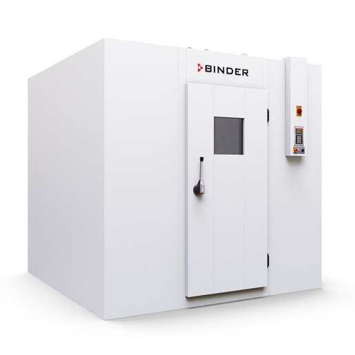
BINDER WIC 1
BINDER WIC 1 — Climate chambers.
The WIC 1 is a walk-in environmental chamber built from 100 mm PU-insulated steel panels with a separate rear-mounted conditioner, providing 12,530 L (12.5 m³) of usable volume and 5.5 m² of floor area. It is the smallest of three WIC sizes, distinguished by a single air baffle and a 2.70 kW single-phase 230 V supply, and is intended for ICH Q1A stability testing and constant-climate storage within 5–50 °C and 20–90 % RH.
BINDER WIC Series — Model Comparison & Selection
Full specifications
| Interior volume | 12530 L |
| Nominal power | 2.7 kW |
| Temperature fluctuation | 0.5 K |
| Temperature uniformity | 1.5 K |
| Article Number mfr | 9800 |
| Depth | 2500 mm |
| Height | 2470 mm |
| Interior height | 2270 mm |
| Interior width | 2400 mm |
| Width | 2600 mm |
| Net weight of the unit (empty) mfr | 776 kg |
| Power frequency | 50 Hz |
| Rated voltage | 200...230 V |
| Unit fuse | 16.0 A |
| Phase (Nominal voltage) mfr | 1 |
| Humidity fluctuation | 2.5 % RH |
| Humidity range | 20...90 % RH |
Description
Construction and series positioning
- Modular walk-in chamber: galvanized, polyester-coated steel panels with 100 mm PU foam insulation (U = 0.21 W/m²K), chrome-nickel steel floor overlay (1.4301, 0.7 mm on 15 mm multiplex, slip resistance R12).
- Separate conditioner (Art. no. 6011-0228) mounted at the rear as standard; front mounting is an option.
- WIC 1 is the smallest variant: 12.5 m³ / 5.5 m² versus WIC 2 (18.5 m³ / 8.2 m²) and WIC 3 (24.5 m³ / 10.8 m²). It uses one air baffle (WIC 2: two, WIC 3: three) and a single shelf set (8012-2240) with 6 uprights and 5 shelf widths.
- Door can be placed on the long or short side for WIC 2 and WIC 3; WIC 1 has a fixed door arrangement per the dimensional drawings.
Working behavior
- Temperature range 5–50 °C with humidity; fluctuation 0.5 K, uniformity 1.5 K, humidity fluctuation 2.5 % RH across the 20–90 % RH range.
- Humidification/dehumidification is supplied with tap water via 1/2" female NPT freshwater and drain connections; the system supports the full 20–90 % RH range.
- Refrigerant R450a (0.737 kg, GWP 547), maximum operating pressure 17 bar.
- Temperature safety device per DIN 12880:2007 (Class 1 on type plate; Class 3.1 on example label) plus adjustable thermal protection for the interior and a door frame heater limited to 55 °C by a separate controller with temperature limiter and two additional fuses in the conditioner.
Installation, connection and control
- Installation time approximately 2 hours with 2 persons; floor elements, wall/ceiling panels and shelves are equipotential-bonded during assembly.
- Electrical connection via junction box containing overcurrent protection (FI) and circuit breakers; main power switch / Emergency Off (EMO) switch and Emergency Stop switches form the safety chain.
- Controller is the SmartPad, which allows setpoint entry for temperature and humidity and can be locked against unauthorized setpoint changes.
- Interior LED lighting (RZB Planox ECO, IP66, 37 W, 4950 lm, motion detector) is wired through the connection box (Art. no. 5001-0055) with 2 × M25 glands for control sensor and 2 × M16 glands for lighting.
- Optional access port, door sill ramp, stainless steel heavy-duty shelves (height 2,007 mm) and trolley ramp are available but not included in base delivery.
Integration & Operating Notes
The site must provide at least 500 mm behind the conditioner, 100 mm to the side and 1.5 m on the door side, with a minimum ceiling height of 2.59 m. The floor must support 0.75 kg/cm³ and a permissible surface load of 50,000 N/m²; steel-wheeled equipment must not enter the chamber, and rubber wheel load is limited to 1000 N/4 cm².
Freshwater inlet and unit drain inlet are both 1/2" female NPT. The humidification/dehumidification system supports 20–90 % RH and is supplied with tap water; water quality per chap. 4.3.1 must be observed, and both supply and drain plumbing must be prepared before commissioning.
Temperature and humidity setpoints are entered on the SmartPad; the terminal can be locked for setpoint entry, which is relevant for validated stability studies. After a power failure the chamber follows a defined behavior described in chap. 7, and required actions must be taken before resuming a study.
Maintenance must be performed at least once a year by licensed electricians or experts authorized by BINDER. An annual repeat electrical inspection is required and recommended under EN 50678:2020 / EN 50699:2020; the same tests are required before initial startup and after any maintenance or repair.
Water must not penetrate the chamber during cleaning, and cleaning while the chamber is turned on is prohibited. Decontamination and chemical disinfection are covered in chap. 9; the chamber has IP20 protection and must not become wet during operation, cleaning or maintenance.
The conditioner (Art. no. 6011-0228) is positioned and screwed to the chamber with a tightening torque of 30 Nm; the silicone gasket must be checked before mounting. Lifting equipment must have a capacity of at least double the load weight, and the conditioner is lifted with 4 persons or mechanical assistance using the supplied lifting brackets.
Selection & Integration Q&A
Pick the WIC 1 when 12.5 m³ / 5.5 m² of floor area covers your study load; it uses one air baffle and a single shelf set (8012-2240). Move to WIC 2 (18.5 m³ / 8.2 m²) or WIC 3 (24.5 m³ / 10.8 m²) when more usable volume or a door on the long/short side is needed.
Provide a single-phase 230 V / 50–60 Hz supply sized for 11.1 A with ±10 % tolerance and a 16 A fuse, plus 1/2" female NPT freshwater and drain connections for the conditioner. The junction box contains the FI protection and circuit breakers.
Minimum clearances are 500 mm rear, 100 mm side and 1.5 m door side, with 2.59 m ceiling height. The floor must support 0.75 kg/cm³ and 50,000 N/m² surface load; steel wheels are not permitted. With the door closed, stay time is 20 min for one person and 10 min for two.
Annual maintenance by BINDER-authorized personnel and a repeat electrical inspection per EN 50678/50699 are mandatory. The accessory pack (8009-1123) and shelf set (8012-2240) are ordered separately; the optional access port, door sill ramp and trolley ramp are not included.