
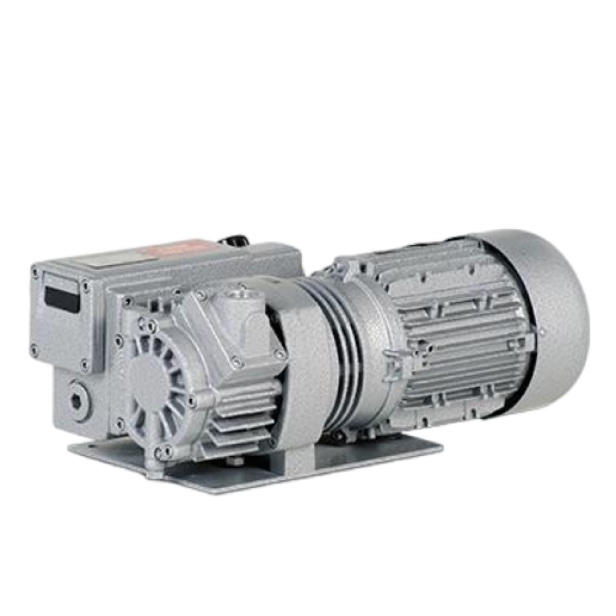
Elmo Rietschle V-VCB
Elmo Rietschle V-VCB — Central Industrial & Medical Vacuum Systems with Motor power 0.9 kW, Noise level 64 dB, Pumping speed 24 m³/h.
The V-VCB 20 is an oil-flooded rotary vane vacuum pump with a flanged standard motor, integrated non-return valve, and air cooling, delivering 20 m³/h at 50 Hz and 24 m³/h at 60 Hz. It achieves an ultimate vacuum of 2 mbar and is distinguished within the V-VCB series by its 0.75 kW motor and 20 m³/h nominal capacity, versus the 23 m³/h of the V-VCB 25. It is intended for continuous evacuation in central industrial vacuum systems where a compact, reliable pump with oil-mist separation is required.
Full specifications
| Motor power | 0.75 kW (50 Hz) 60 Hz: 0.9 kW |
| Noise level | 63 dB (50 Hz) 60 Hz: 64 dB |
| Pumping speed | 20 m³/hour (50 Hz) 60 Hz: 24 m³/hour |
| Ultimate pressure | 2 mbar |
| Rotational speed | 2850 rpm (50 Hz) 60 Hz: 3420 rpm |
| Suction capacity mfr | 20 m3/h (50 Hz) |
| Suction capacity mfr | 24 m3/h (60 Hz) |
| Motor efficiency mfr | 84.5 % (60 Hz) |
| Saugvermögen / Suction capacity mfr | 20 m3/h (50 Hz) |
| Saugvermögen / Suction capacity mfr | 24 m3/h (60 Hz) |
| Enddruck / Ultimate vacuum mfr | 2 mbar (abs.) |
| Motorwirkungsgrad / Motor efficiency mfr | 84.5 % (60 Hz) |
| Weight | 21 kg |
| Voltage | 230 / 400 V ± 10 % V |
| Rated voltage mfr | 220 / 380 V ±10% V (60 Hz) |
| Motor rating mfr | 0.9 kW (60 Hz) |
| Current drawn mfr | 3.52 / 2.03 A (60 Hz) |
| Bemessungsspannung / Rated voltage mfr | 220/380 V (±10%) |
| Motorleistung / Motor rating mfr | 0.75 kW (50 Hz) |
| Motorleistung / Motor rating mfr | 0.9 kW (60 Hz) |
| Stromaufnahme / Current drawn mfr | 3.52/2.03 A (60 Hz) |
| Andere Spannungen / Other voltages (Vx) mfr | 200 Δ / 346 Y V (50 Hz) |
| Andere Spannungen / Other voltages (Vx) mfr | 200 Δ / 230 Y / 400 V (60 Hz) |
| Andere Spannungen / Other voltages (Sx) mfr | 200 Δ / 230 Y / 400 V (50 Hz) |
| Andere Spannungen / Other voltages (Sx) mfr | 230 Δ / 460 Y V (60 Hz) |
| Andere Spannungen / Other voltages (Ux) mfr | 330 Δ / 380 Y / 660 V (50 Hz) |
| Andere Spannungen / Other voltages (Ux) mfr | 220 Δ / 380 Y / 440 V (60 Hz) |
| Andere Spannungen / Other voltages (Tx) mfr | 200 Δ / 400 Y / 690 V (50 Hz) |
| Andere Spannungen / Other voltages (Tx) mfr | 230 Δ / 400 Y / 460 V (60 Hz) |
| Bemessungsspannung / Rated voltage (alt var) mfr | 220 / 380 V ± 10 % V |
| Oil capacity mfr | 0.35 l |
| Öleinfüllmenge / Oil capacity mfr | 0.35 l |
| Protection rating | IP 55 |
| Cooling type | Luftkühlung / Air cooling |
| Average noise level mfr | 64 dB(A) (60 Hz) |
| Mittlerer Schalldruckpegel / Average noise level mfr | 63 dB(A) (50 Hz) |
| Mittlerer Schalldruckpegel / Average noise level mfr | 64 dB(A) (60 Hz) |
Description
Construction and Series Positioning
The V-VCB 20 is a single-stage, oil-flooded rotary vane pump directly coupled to a three-phase standard motor via a flanged connection. The pump housing integrates an oil/oil-mist separator on the discharge side that returns separated oil to the lubrication circuit. A fan mounted between the pump and motor provides forced air cooling. An integrated non-return valve prevents back-ventilation of the evacuated system after shutdown. Within the V-VCB series, this model is the smaller of two displacements: the V-VCB 20 offers 20 m³/h at 50 Hz (24 m³/h at 60 Hz), while the V-VCB 25 provides 23 m³/h at 50 Hz. The V-VCB 20 is therefore selected when the required pumping speed is moderate and space or power is limited; the V-VCB 25 is preferred for higher flow demands. Both models share the same construction and options, including a gas ballast valve variant for condensable vapours.
Operating Behavior and Limits
The pump achieves an ultimate pressure of 2 mbar (abs.) and is designed for continuous operation with intake pressures between 2 and 200 mbar (abs.) at 50 Hz, or 2 and 150 mbar (abs.) at 60 Hz. Operating outside these ranges risks oil leakage through the exhaust. The maximum permissible back pressure on the exhaust side is +100 mbar; exceeding this can damage the pump or create a safety hazard. When evacuating closed volumes, the volume must not exceed 2% of the nominal pumping capacity to avoid oil carry-over and overheating. The pump is not suitable for frequent switching: at around 10 starts per hour or more, or at elevated ambient temperatures, the motor winding and bearings may exceed their temperature limits, and the manufacturer should be consulted. The motor is rated 0.75 kW at 50 Hz and 0.9 kW at 60 Hz, with speeds of 2850 and 3420 rpm respectively. Average noise level is 63 dB(A) at 50 Hz and 64 dB(A) at 60 Hz. The pump weighs 21 kg and has an oil capacity of 0.35 l.
Installation, Connection, and Control
Installation requires a horizontal mounting surface with a maximum inclination of 1° in all directions, and the floor must be able to support the weight. At least 30 cm of free space must be provided around the machine for maintenance access, and cooling air inlets/outlets must be at least 15 cm from adjacent walls. The pump must not be subjected to external vibration, and hot exhaust air from other machines must not enter the cooling air intake. The suction and exhaust connections are made via flanges; pipes should be screwed in by hand only, and flexible connections are recommended to avoid stress. The exhaust line must not be restricted or fitted with a filter, and it must be sized to keep back pressure below +100 mbar. The electrical connection must be performed by a qualified electrician in accordance with EN 60204. The motor is designed for 230/400 V ±10% at 50 Hz or 220/380 V ±10% at 60 Hz. The actual supply must be within ±5% of nominal voltage and ±2% of nominal frequency unless otherwise stated on the motor data plate. A main switch and motor protection switch must be provided by the operator. The motor complies with DIN EN 60034, has IP 55 protection and insulation class F. The direction of rotation must be checked before commissioning: with the motor fan viewed, rotation must be anti-clockwise; a phase sequence indicator can be used, and a brief start of no more than two seconds is permitted for the check. After correcting rotation, the pump should run for two minutes and oil topped up to the upper edge of the sight glass, repeating until all oil pipes are filled. The pump is air-cooled and requires adequate room ventilation; ambient and inlet temperatures must be between 5 and 40 °C. The integrated non-return valve must not be removed. If the pump is stopped with the connected system under vacuum, the connected pipe should be vented to atmospheric pressure to prevent oil backflow.
Integration & Operating Notes
The exhaust line must be sized to avoid restrictions; a filter or any component that increases back pressure above +100 mbar can cause impermissible pressure inside the pump, leading to component damage or injury. No filter may be installed on the exhaust side.
When evacuating a closed system, the volume must not exceed 2% of the nominal pumping capacity. Larger volumes require a different pump or method to avoid oil leakage and overheating.
The pump must be set up horizontally on a plane floor able to carry its weight. Exceeding this inclination can impair lubrication and operation, leading to damage.
This space is required for maintenance access to the oil filling point, sight glass, oil drain, and oil separator housing. Cooling air inlets and outlets must be at least 15 cm from adjacent walls to ensure sufficient cooling air flow.
With the motor fan viewed, rotation must be anti-clockwise. Use a phase sequence indicator (clockwise rotating field) and perform a brief start of no more than two seconds. Wrong rotation can cause injury and machine damage.
The motor is designed for 230/400 V ±10% at 50 Hz or 220/380 V ±10% at 60 Hz, but the actual supply must be within ±5% of nominal voltage and ±2% of nominal frequency unless otherwise stated on the motor data plate. Exceeding these tolerances may cause loss of power or damage.
The oil level must be checked daily in the sight glass. Low oil level can damage the pump. Leaks or visible oil mist in the exhaust air require immediate determination of the cause and replacement of the oil separator element in good time.
Incorrect oil viscosity can cause overheating, insufficient pumping capacity, or final pressure issues. The oil separator element must be changed when dirty, and coupling rubbers must be replaced when worn.
Operation outside this range requires consultation with the manufacturer; otherwise overheating or oil viscosity issues may occur. Output reduction is noticeable when installed at more than 1000 m above sea level.
Selection & Integration Q&A
Choose the V-VCB 20 when your required pumping speed is around 20 m³/h at 50 Hz and you want a more compact, lower-power unit (0.75 kW). The V-VCB 25 delivers 23 m³/h at 50 Hz and is better for higher flow demands. Both share the same construction and options, so selection is primarily based on required capacity.
The exhaust line must not be restricted or fitted with a filter. Maximum permissible back pressure is +100 mbar. Exceeding this can cause impermissible pressure, component damage, or injury. Size the exhaust line to keep back pressure below this limit and avoid liquid accumulation.
The motor is IP 55 and suitable for indoor industrial environments. The pump must not be subjected to external vibrations, and hot exhaust air from other machines must not enter the cooling air intake. Ambient temperature must be 5–40 °C.
The base delivery does not include oil (ISO VG 46 per DIN ISO 3448 must be ordered separately), a main switch, motor protection switch, or flexible connections. The oil separator element and coupling rubbers are wear parts to be replaced as needed. A gas ballast valve is available as an option.