
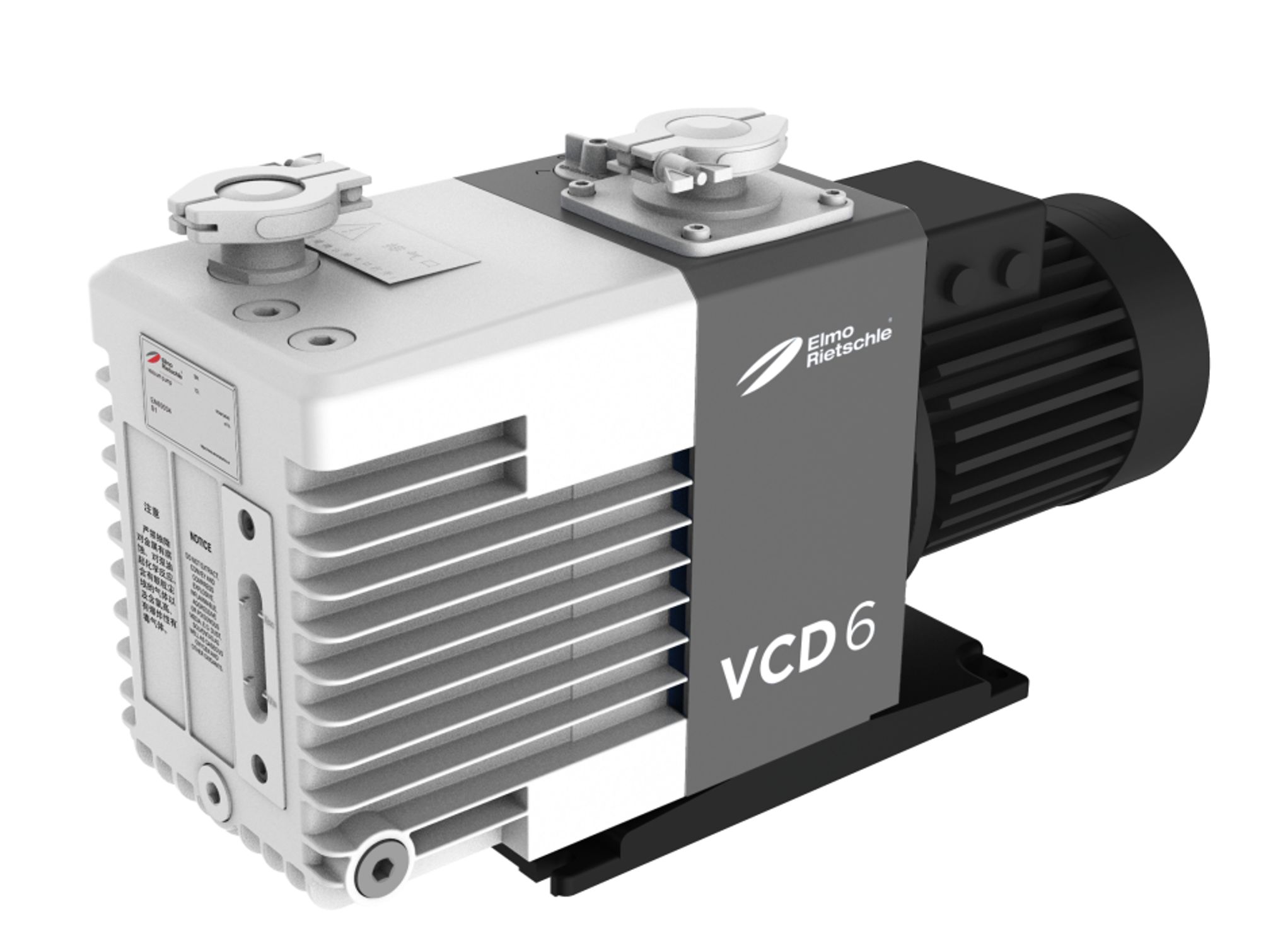
Elmo Rietschle VCD 40
Elmo Rietschle VCD 40 — Central Industrial & Medical Vacuum Systems with Motor power 1.1 kW, Noise level 67 dB, Pumping speed 48 m³/h.
Oil-flooded rotary vane vacuum pump VCD 40, standard design, delivers 40 m³/h at 50 Hz (48 m³/h at 60 Hz) and an ultimate vacuum of 0.5 mbar (abs.). Its permissible intake pressure range of 0.5–500 mbar (abs.) distinguishes it from the IV variant (below 100 mbar) and XD variant (3.0–500 mbar) within the VCD series. It is intended for continuous evacuation and holding duties in central industrial vacuum systems where the process pressure stays above 0.5 mbar.
Elmo Rietschle VCD Series — Model Comparison & Selection
Full specifications
| Motor power | 1.1 kW (50 Hz) |
| Noise level | 62 dB (50 Hz) 60 Hz: 67 dB |
| Pumping speed | 40 m³/hour (50 Hz) 60 Hz: 48 m³/hour |
| Ultimate pressure | 0.5 mbar |
| Rotational speed | 1450 rpm (50 Hz) 60 Hz: 1750 rpm |
| Nominal suction capacity mfr | 40 m3/h (50 Hz) |
| Nominal suction capacity mfr | 48 m3/h (60 Hz) |
| Motor efficiency mfr | 84.8 % (50 Hz) |
| Exhaust air outlet mfr | G 1 1/4 |
| Correct amount of oil mfr | 3.0 l |
| a mfr | 600 (50 Hz) |
| a1 mfr | 316.5 |
| b mfr | 336 |
| c mfr | 270 (50 Hz) |
| c1 mfr | 267 |
| d mfr | 113.5 |
| f mfr | 287.5 |
| f1 mfr | 23.5 |
| l mfr | 90.5 |
| o mfr | 236 |
| p mfr | 242 |
| q mfr | 168.5 |
| r mfr | 104.5 |
| t mfr | M 25 x 1.5 |
| R mfr | G 11/4 |
| R1 mfr | G 11/4 |
| ZFP mfr | 145 (06) |
| ZVF mfr | 32 (53) |
| Motor starter mfr | 63 / 40 (50 Hz) |
| Motor starter mfr | 63 / 40 (60 Hz) |
| Weight | 55 kg (50 Hz) 60 Hz: 55 kg |
| Height | 267 mm |
| Length | 585.5 mm (50 Hz) 60 Hz: 585.5 mm |
| Width | 316.5 mm |
| Current | 4.07 / 2.34 A (50 Hz) |
| Voltage | 230 / 400 V (50 Hz) 60 Hz: 265 / 460 V |
| Rated voltage mfr | 265 / 460 V ±10% V (60 Hz) |
| Motor rating (alt 50 Hz) mfr | 1.25 kW (50 Hz) |
| Current consumption (alt 50 Hz) mfr | 4.89 / 2.81 A (50 Hz) |
| Inlet connection | G 11/4 |
| Height (without terminal box) mfr | 267 mm |
| Oil capacity mfr | 3.0 l |
| Average noise level mfr | 67 dB(A) (60 Hz) |
| Sound pressure level (max.) mfr | 66 dB(A) (50 Hz) |
| Sound pressure level (max.) mfr | 70 dB(A) (60 Hz) |
| Sound pressure level (max.) (alt 50 Hz) mfr | 66 dB (50 Hz) |
| Sound pressure level (max.) (alt 60 Hz) mfr | 70 dB (60 Hz) |
| Sound pressure level (max.) EN ISO 3744 mfr | 66 dB(A) (50 Hz) |
| Sound pressure level (max.) EN ISO 3744 mfr | 70 dB(A) (60 Hz) |
Description
Construction and series positioning
- The VCD 40 is an oil-flooded rotary vane pump with a flange-mounted IE3 motor, rotor bearings on both sides, and an oil/air heat exchanger.
- Within the VCD series, the standard design covers the full intake pressure range of 0.5 to 500 mbar (abs.). The IV variant is restricted to below 100 mbar (abs.) and has no gas ballast valve; the XD variant is for high water-vapour tolerance and covers 3.0 to 500 mbar (abs.).
- The VCD 40 is the smallest model in the documented VCD series; larger models are available for higher suction capacities.
- Vacuum and exhaust connections are both G 1 1/4; oil capacity is 3.0 l; weight is 55 kg.
Behaviour under load and in different media
- The pump is designed for continuous operation with intake pressure between 0.5 and 500 mbar (abs.). Operation outside this range risks oil leakage through the outlet.
- For permanent operation above 100 mbar (abs.), the next larger motor output must be used; the standard 1.1 kW motor is not intended for continuous duty at higher pressures.
- When evacuating closed systems, the volume to be evacuated must not exceed 2% of the nominal suction capacity (i.e., about 0.8 m³/h at 50 Hz) to avoid overheating and oil leakage.
- Counter pressure on the outlet side is permissible only up to +0.1 bar; the exhaust line must be sized accordingly.
- The pump handles air and non-aggressive gases; versions for gases with raised oxygen share and high water-vapour tolerance are available as separate variants.
Installation, connection and operation
- Cooling air inlets and outlets must be at least 30 cm from adjacent walls; maintenance space of at least 40 cm around the machine is required.
- The machine must be operated at an ambient and suction temperature between 12 and 40 °C. At altitudes above 1000 m, a reduction in power is noticeable and the manufacturer must be consulted.
- Electrical connection: 230/400 V ±10 % at 50 Hz or 265/460 V ±10 % at 60 Hz. The manual specifies permissible voltage deviation of ±5 % and frequency deviation of ±2 % without derating; outside these limits, derating or consultation is required.
- A motor protection switch with delayed switch-off is recommended to accommodate temporary excess current when starting cold.
- The direction of rotation must be checked at commissioning. The coupling sprocket must be inspected at least once a year and replaced if worn or damaged.
- Oil viscosity must comply with ISO VG 100 (DIN ISO 3448). The first oil change is due after 500 hours; subsequent changes every 500–2000 hours depending on contamination. Oil separator elements (3 required for VCD 40) must be replaced every 2000 operating hours or when filter resistance reaches 0.7 bar.
Integration & Operating Notes
Operating outside this range can cause oil leakage through the outlet or inadequate lubrication. For processes that regularly run below 100 mbar (abs.), the IV variant is the correct choice; for wet or high-water-vapour processes, the XD variant (3.0–500 mbar) should be selected instead of the standard pump.
When evacuating a closed volume, the volume must not exceed 2% of the nominal suction capacity (about 0.8 m³/h at 50 Hz for the VCD 40). Larger volumes require a larger pump or a buffer vessel to prevent overheating and oil leakage during evacuation.
The exhaust line must be sized to keep counter pressure at or below +0.1 bar. Restrictions, long exhaust runs, or undersized silencers can raise back pressure, leading to increased oil carry-over and reduced pumping speed.
Cooling air inlets and outlets must be at least 30 cm from adjacent walls, and at least 40 cm of free space must be maintained around the machine for maintenance access. Insufficient clearance causes overheating and makes oil changes and filter replacement difficult.
A motor protection switch with delayed switch-off is recommended to accommodate the temporary excess current drawn when starting cold. A standard instantaneous-trip breaker may trip unnecessarily during cold starts; the protection setting should allow short-term overload without compromising winding protection.
The manual permits voltage deviation of ±5% and frequency deviation of ±2% without derating. Outside these limits, derating or consultation with the manufacturer is required. Note that the data sheet states ±10% for rated voltage; the tighter manual limit should govern selection of supply quality.
The machine must only be operated at an ambient temperature and suction temperature between 12 and 40 °C. For temperatures outside this range, the manufacturer must be consulted. At altitudes above 1000 m, a reduction in power is noticeable and requires consultation.
The first oil change is due after 500 operating hours; subsequent oil changes every 500–2000 hours depending on contamination. Use only oil with viscosity ISO VG 100 (DIN ISO 3448). Oil capacity is 3.0 l. Oil separator elements (3 required) must be replaced every 2000 hours or when filter resistance reaches 0.7 bar.
Selection & Integration Q&A
Choose the standard VCD 40 when the process pressure stays between 0.5 and 500 mbar (abs.) and the gas is dry. For continuous operation below 100 mbar (abs.), select the IV variant (no gas ballast). For high water-vapour loads, select the XD variant (3.0–500 mbar).
Both vacuum and exhaust connections are G 1 1/4. The exhaust line must be sized to keep back pressure at or below +0.1 bar. Use mating fittings rated for the application and ensure the line is free from restrictions.
The pump is designed for continuous operation. If switched on about 10 times per hour or more, or at higher ambient/intake temperatures, the excess temperature limit of the motor winding and bearings may be exceeded; consult the manufacturer. For permanent operation above 100 mbar (abs.), a larger motor is required.
The base delivery does not include oil (ISO VG 100, 3.0 l required), oil separator elements (3 required), or a motor protection switch. These must be ordered separately. The first oil change is after 500 h; separator elements every 2000 h or at 0.7 bar filter resistance.