
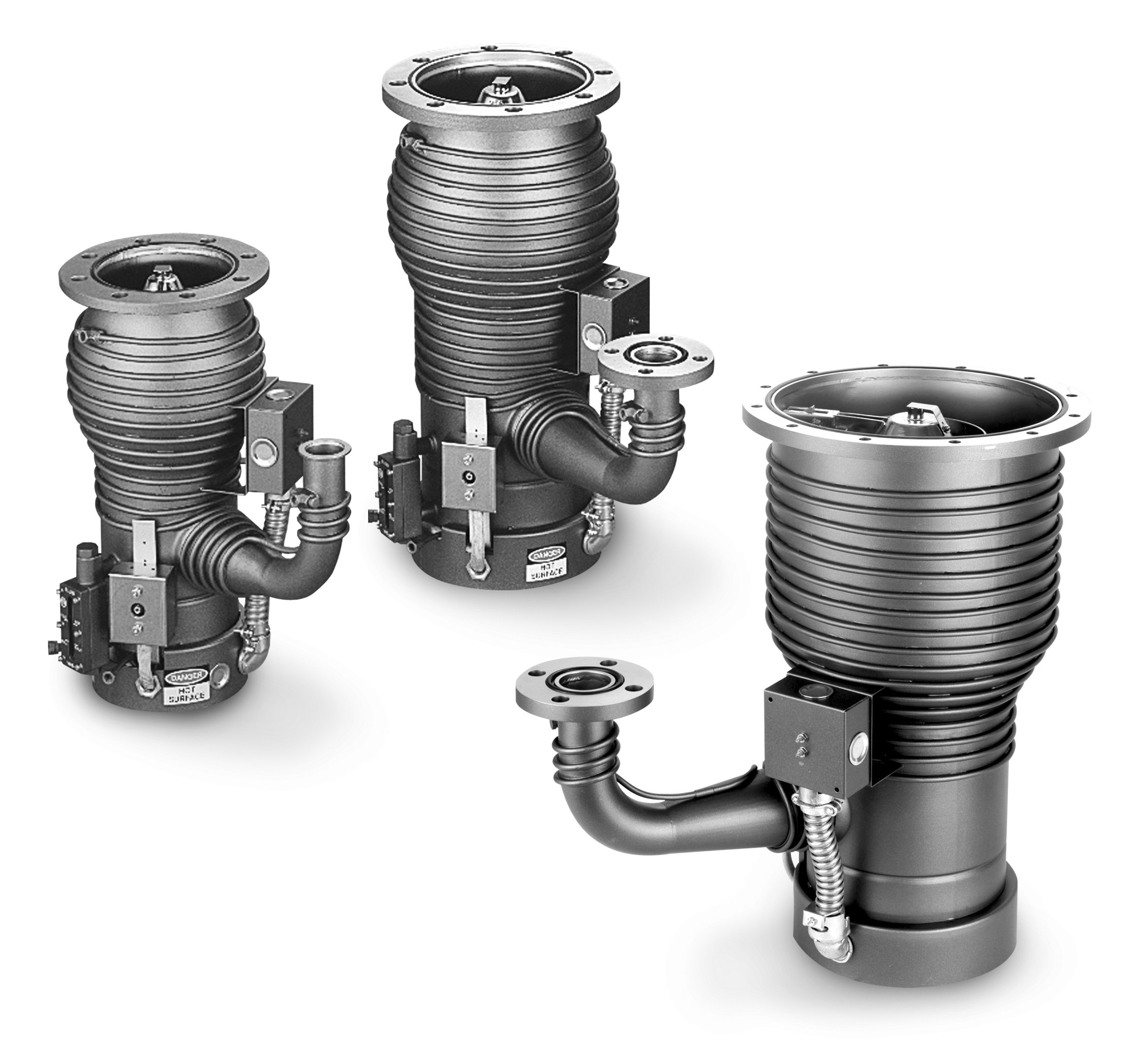
Agilent Technologies VHS-4 Diffusion Pump
Agilent Technologies VHS-4 Diffusion Pump — Vacuum technologies with Motor power 1.45 kW, Pumping speed 4320 m³/h.
The VHS-4 is a 4-inch, 4-stage stainless-steel diffusion pump rated 1200 l/s air with standard cold cap, distinguished within the VHS series by its 10 cfm backing-pump requirement and 1.2 Torr·l/s maximum throughput. It serves as the high-vacuum stage behind a 10 cfm forepump in analytical and laboratory systems.
Agilent Technologies Small Diffusion Pumps Series — Model Comparison & Selection
| Model | Motor power, kW | Pumping speed, m³/h | Cooldown time, minutes | Cooling water pressure, psi | Diffusion pump pumping speed, L/s | Warm up time, minutes |
|---|---|---|---|---|---|---|
| VHS-4 Diffusion Pump Current | 1.45 | 4320 | 10 | 15 | 50 | 10 |
| VHS-250 Diffusion Pump | 1.45 | 4320 | 10 | 15 | 50 | 10 |
| VHS-6 Diffusion Pump | 1.45 | 4320 | 10 | 15 | 50 | 10 |
Full specifications
| Motor power | 1450 Watts |
| Pumping speed | 1200 l/s |
| Cooldown Time | 10 minutes |
| Cooldown Time (using Quick Cool Coil) | 10 minutes |
| Diffusion Pump Pumping Speed | 50 L/s |
| Extended Cold Cap | 120 V |
| Heater Power | 1450 watts |
| Warm-up Time | 10 minutes |
| Vacuum gauge measurement range mfr | 6 pressure |
| Dry scroll pump typical size mfr | 3...30 h |
| Turbomolecular pump pumping speed mfr | 70...3 L/s |
| Optimum Operating Range mfr | 9 mbars |
| Maximum Forepressure mfr | 0.65 Torr |
| Backstreaming Rate at Pump Inlet mfr | 5 minute |
| Backing Pump Size mfr | -4 throughput |
| Recommended Jet Assembly mfr | 4 steel |
| Maximum Throughput mfr | 1.2 l/s |
| Optimum Operating Range (Torr) mfr | 1 |
| Maximum Throughput (Torr-l/s) mfr | 1.2 Torr |
| Poor system pressure mfr | System dirty. dirty. |
| Poor ultimate pressure mfr | Water in Quick Cool Coil. Coil. |
| Slow pumpdown (prolonged cycle after checking gas load conditions) mfr | Malfunctioning pump assembly Improperly located |
| Electrical Requirements mfr | 120 phase |
| Pressure drop across coils mfr | -4 psi |
| Foreline Baffle mfr | Stacked half moon moon |
| Water Connections mfr | 1 FPT |
| Installation mfr | 2 |
| Heater circuit resistance (ohms) — 120 V mfr | 9.4 |
| Heater circuit resistance (ohms) — 208 V mfr | 28.3 |
| Heater circuit resistance (ohms) — 240 V mfr | 37.7 |
| Clearance (for heater removal) mfr | 6 minimum |
| Materials — Body, Flanges, Foreline, Baffle mfr | stainless steel steel |
| Materials — Jet Assembly mfr | stainless steel steel |
| Materials — Cold Cap mfr | nickel-plated copper copper |
| Rough pump pressure before startup mfr | 0.5 Torr |
| Heater clamp bolt torque mfr | 250 pounds |
| Shipping Weight | 55 pounds |
| Turbomolecular pump controller protection class mfr | 54 |
| Inlet Flange, Nominal Size mfr | 250 F |
| Foreline Flange, Nominal Size mfr | 1 ASA |
| Fluid Charge mfr | -4 cc |
| VHS-4 oil charge mfr | 300 cc |
| VHS-6 and VHS-250 oil charge mfr | 500 cc |
| VHS-4 fluid charge mfr | 300 cc |
| VHS-6 and VHS-250 fluid charge mfr | 500 cc |
| Cooling Water Pressure | 15 psi |
| Cooling Water Requirements mfr | 60 °F |
| Cooling Water Flow mfr | 0.25 gpm |
| Thermal Switches mfr | 300 °F |
| Environmental mfr | 113 °F |
| Altitude mfr | 6562 |
| Materials — Body Cooling Coils mfr | copper copper |
| Materials — Quick Cooling Coil mfr | stainless steel steel |
| VHS-4 cooling water flow mfr | 0.15 gpm |
| VHS-6 and VHS-250 cooling water flow mfr | 25 gpm |
| Standard cold cap mfr | 240 |
Description
Construction and series positioning
- The VHS-4 uses a 4-stage, self-aligning stainless-steel jet assembly and a standard cold cap; it is the smallest of the VHS-4 / VHS-6 / VHS-250 family covered by the user manual.
- Against siblings: the VHS-250 reaches 3700 l/s air (4600 l/s helium) and needs a 17 cfm backing pump, while the VHS-4 is limited to 1200 l/s air and a 10 cfm forepump. The VHS-4 is the choice when the gas load fits its 1.2 Torr·l/s throughput ceiling and chamber size does not justify a larger stack.
Behavior under load and process window
- Maximum throughput is 1.2 Torr·l/s (1.6 mbar·l/s); the backing pump must hold foreline pressure below the 0.65 Torr maximum forepressure (no load) or the jet stops pumping.
- Warm-up and cooldown are each 10 minutes; the pump should not be vented before cooldown completes.
- Prolonged operation at high throughput above 10⁻³ Torr raises chamber contamination risk, so the pump belongs in the high-vacuum regime, not as a roughing stage.
Installation, control and operation
- Cooling water must be supplied at 60–80 °F (15–26 °C) inlet; flow for the VHS-4 is not separately printed in the digest (0.25 gpm at 15 psi is stated for VHS-6/VHS-250).
- Thermal switches are manual-reset at 300 °F (149 °C); maximum ambient is 113 °F (45 °C).
- Startup is blocked if safety circuits, flow switches, interlocks or thermostats keep the contactor open; leakage checks concentrate on inlet/foreline connections, drain and fill plugs, compression fittings and threaded joints.
Integration & Operating Notes
The 0.65 Torr maximum forepressure is a no-load limit; if the backing pump cannot hold the foreline under it, the diffusion jet stalls and chamber pressure rises. Size and valve the foreline so that the 10 cfm backing pump maintains margin below this threshold at the expected gas load.
Sustained high-throughput operation at pressures above 10⁻³ Torr (1.33×10⁻³ mbar) increases backstreaming and chamber contamination. Use the pump only after the chamber has been roughed below this level, and avoid processes that hold the inlet in the transition regime.
Water outside this temperature band degrades jet performance or cooling; the manual states 60/80 °F as the maximum inlet range for the series. Provide a supply that holds this window, and note that the 0.25 gpm at 15 psi flow figure is printed for VHS-6/VHS-250, not for the VHS-4.
Startup is inhibited when protective devices — flow switches, interlocks, thermostats — prevent the contactor from staying closed. During commissioning, verify each utility and interlock in the start circuit; a pump that refuses to start is usually a tripped protective device, not a heater fault.
The thermal switches are manual-reset types set at 300 °F (149 °C). After a trip, the pump must cool before the switch can be reset; repeated trips point to lost cooling water or excessive heater duty and should be investigated before resetting again.
The maximum ambient temperature for the series is 113 °F (45 °C). Enclosures or cabinets that trap heat around the pump body can exceed this even when room temperature is acceptable, so verify local temperature at the pump, not only at the room sensor.
Selection & Integration Q&A
Pick the VHS-4 when the gas load is at or below 1.2 Torr·l/s and 1200 l/s air pumping speed suffices; it also needs only a 10 cfm backing pump. The VHS-250 delivers 3700 l/s air and 4600 l/s helium but requires a 17 cfm forepump, so it is the choice for larger chambers and gas loads.
A 10 cfm backing pump is specified for maximum throughput on the VHS-4, and the foreline must stay below the 0.65 Torr maximum forepressure. Confirm the forepump holds that margin at the process gas load; otherwise the jet stalls before reaching rated speed.
Ambient must stay at or below 113 °F (45 °C), cooling water inlet within 60–80 °F (15–26 °C), and the pump needs 10 minutes warm-up and 10 minutes cooldown. Avoid prolonged high-throughput operation above 10⁻³ Torr, which raises contamination risk.
Plan for pump fluid charge and periodic fluid inspection, cold-cap and jet-assembly removal for cleaning, heater replacement, and manual reset of the 300 °F thermal switches. Leak checks cover inlet and foreline connections, drain and fill plugs, compression fittings and threaded joints; these service parts are not part of the base pump.