
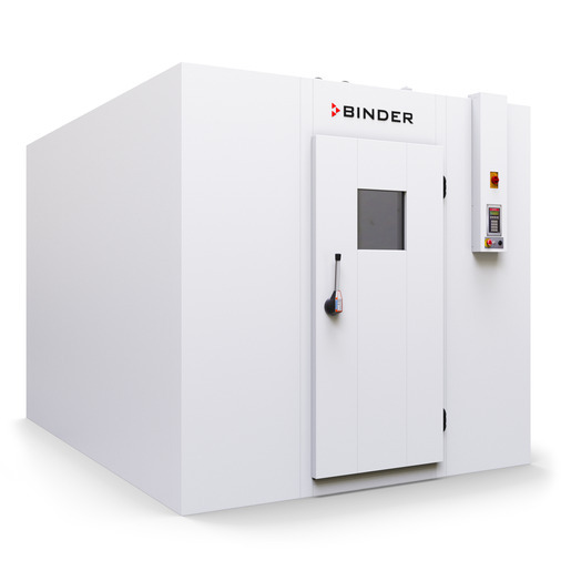
BINDER WIC 2
BINDER WIC 2 — Climate chambers.
The WIC 2 is a walk-in environmental stability chamber built from 100 mm PU-insulated steel panels with a separate rear-mounted conditioner, offering 18.5 m³ usable volume and 8.2 m² floor area. It holds 5–50 °C and 20–90 % RH for ICH Q1A stability testing, sitting between the WIC 1 and WIC 3 in the series. Its 230 V single-phase 2.7 kW conditioner and 1/2" NPT water connections define the site services.
BINDER WIC Series — Model Comparison & Selection
Full specifications
| Interior volume | 18523 L |
| Nominal power | 2.7 kW |
| Temperature fluctuation | 0.5 K |
| Temperature uniformity | 1.5 K |
| Article Number mfr | 9800 |
| Depth | 3600 mm |
| Height | 2470 mm |
| Interior height | 2270 mm |
| Interior width | 2400 mm |
| Width | 2600 mm |
| Net weight of the unit (empty) mfr | 981 kg |
| Power frequency | 50 Hz |
| Rated voltage | 230 V |
| Unit fuse | 16.0 A |
| Phase (Nominal voltage) mfr | 1 |
| Humidity fluctuation | 2.5 % RH |
| Humidity range | 20...90 % RH |
Description
Construction and series positioning
- Modular walk-in chamber: galvanized, polyester-coated steel panels with 100 mm PU foam (U = 0.21 W/m²K), 0.7 mm chrome-nickel steel floor overlay (1.4301) on 15 mm multiplex, slip resistance R12.
- WIC 2 provides 18.5 m³ / 8.2 m² (volume / floor area plus ramp), between WIC 1 (12.5 m³ / 5.5 m²) and WIC 3 (24.5 m³ / 10.8 m²). Door can be placed on long or short side for WIC 2 and WIC 3.
- Conditioner (Art. no. 6011-0228) is a separate unit mounted at the rear by default, front mounting optional; it is screwed to the chamber at 30 Nm.
- Interior air distribution uses 2 air baffles for WIC 2 (WIC 1: 1, WIC 3: 3); the sensor box mounts on the first air baffle.
Behavior and process envelope
- Temperature range 5–50 °C, humidity 20–90 % RH, with fluctuation figures of ±0.5 K and ±2.5 % RH under the stated conditions.
- Humidification/dehumidification is tap-water based via freshwater and drain connections, both 1/2" female NPT.
- Refrigerant R450a (0.737 kg, GWP 547), maximum operating pressure 17 bar; type-plate example for the series shows 2.70 kW / 11.1 A at 230 V, 1 N~, 50/60 Hz, ±10 % voltage tolerance.
- Adjustable thermal protection guards the interior against overtemperature; door frame heater is separately controlled with a 55 °C maximum setpoint and temperature limiter.
Installation, control and operation
- Assembly is modular and takes approximately 2 hours with 2 persons; the conditioner is lifted with 4 persons or mechanical assistance using supplied brackets, with hoisting capacity at least double the load.
- Electrical connection is via a junction box containing overcurrent protection and circuit breakers; the main power switch / Emergency Off (EMO) switch and Emergency Stop switches form the safety chain.
- The SmartPad controller handles temperature and humidity setpoints and can be locked against setpoint entry; behavior during and after power failure is defined in the manual.
- Interior LED lighting (RZB Planox ECO, IP66, 37 W, 4950 lm, motion detector) is mounted with clips 100 mm from each lamp end; chamber IP protection is 20.
Integration & Operating Notes
The conditioner needs rear clearance for air circulation and service access, and the door side must remain free for loading and ramp use. Ceiling height must be at least 2.59 m, and the floor must support 0.75 kg/cm³ plus the specified surface and wheel loads.
The floor overlay permits a surface load of 50,000 N/m² and a rubber-wheel load of 1000 N/4 cm²; steel wheels are explicitly not passable. Plan trolleys and racks with rubber wheels and verify the access route load capacity before moving goods in.
One person may stay inside with the door closed for 20 minutes, two people for 10 minutes; more than two people with the door closed is not allowed. The door can be opened from inside at any time even when locked, but operating procedures must enforce these limits.
The main power switch / Emergency Off switch and Emergency Stop switches are wired into the safety chain, and the adjustable thermal protection plus door frame heater temperature limiter protect the interior. These devices must not be bypassed; the SmartPad terminal can be locked to prevent unauthorized setpoint changes.
Maintenance must be performed at least once a year by licensed electricians or BINDER-authorized experts, and an annual repeat electrical inspection is required, recommended under EN 50678:2020 / EN 50699:2020. The same electrical tests are required before initial startup and after any maintenance or repair.
Water must not penetrate the chamber during cleaning, and cleaning while the chamber is turned on is prohibited. The chamber is IP20 and must not become wet during operation, cleaning or maintenance; plan cleaning as a shutdown procedure with the interior dried before restart.
The conditioner is positioned and screwed to the chamber with a tightening torque of 30 Nm after checking the silicone gasket. Use a torque wrench to ensure sealing and mechanical integrity; the conditioner is lifted with 4 persons or mechanical assistance using the supplied brackets.
Selection & Integration Q&A
Pick the WIC 2 when the required usable volume and floor area fall between the WIC 1 (12.5 m³ / 5.5 m²) and WIC 3 (24.5 m³ / 10.8 m²): the WIC 2 offers 18.5 m³ / 8.2 m². All three share the 5–50 °C and 20–90 % RH envelope; the WIC 2 also allows the door on the long or short side, as does the WIC 3.
Provide 1/2" female NPT freshwater and drain connections for the conditioner, and a 230 V 1 N~ 50/60 Hz supply sized for the 2.70 kW / 11.1 A conditioner with ±10 % tolerance (WIC 2 spec sheet: 2.7 kW, 50 Hz, 16 A fuse). The junction box contains the overcurrent protection and circuit breakers.
Annual maintenance by licensed electricians or BINDER-authorized experts and an annual repeat electrical inspection (EN 50678:2020 / EN 50699:2020) are required. Order the WIC 2 accessory pack 8009-1172, shelf set 8012-2241 (8 uprights, 3 cross braces, 7 shelves), and the connection box 5001-0055 with M25/M16 cable glands; tools are not included.