
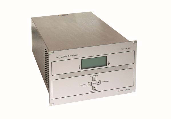
Agilent Technologies Turbo V 1001
Agilent Technologies Turbo V 1001 — Turbomolecular Vacuum Pumps.
The Turbo-V 1001 is a turbomolecular pump driven by the dedicated Turbo-V 1001 Rack Controller (rear-panel variant X3501-64003), a maintenance-free rack- or bench-mounted electronics unit. The controller governs pump start/stop, braking, vent/drain valve sequencing and external fan output, and exposes full telemetry over RS-232/RS-485 and programmable logic I/O. It is the electronics half of the pumping system: the pump itself is not described in the supplied facts, so all ratings below belong to the controller.
Direct drop-in replacements
Full specifications
| Output power | expressed in W |
| Error code mfr | Bit description: see the following figure figure |
| Output for pump: Power during pump ramp-up mfr | 450 maximum |
| Power normal (pump water cooled) mfr | 450 maximum |
| Power normal (pump air cooled) mfr | 300 maximum |
| Power cable mfr | 3 long |
| Pump cable mfr | 5 cable |
| Protection category mfr | 20 |
| Installation category mfr | II II |
| Turbo-V vent mfr | 3501 |
| CHECK CONNECTION TO PUMP mfr | Wrong connection between the pump and the contro |
| Controlled venting deceleration range mfr | 3 Hz/s |
| Pump Bearing Overtemperature Trip | 60 °C |
| Pump bearing temperature mfr | expressed in °C °C |
| Weight (both models) mfr | 6.3 kg |
| Frequency | 50...60 Hz |
| Power consumption | 800 maximum |
| Pump current mfr | expressed in mA dc mA dc dc |
| 3 phase voltage mfr | expressed in Vrms Vrms |
| Driving frequency mfr | expressed in Hz Hz |
| Rotational frequency mfr | in Hz Hz |
| Cooling fan control voltage mfr | 24 Vdc |
| Input: Voltage mfr | 100 phase |
| Fuse: Mains mfr | 2 fuses |
| Controller Transformer Overtemperature Trip | 65 °C |
| Controller internal temperature mfr | in °C °C |
| Serial communication (T-Plus kit) mfr | 232 software |
| Turbo-V 1001 Rack Controller mfr | 3501 |
| T-Plus communication software and serial cable kit mfr | 969 |
| Mains cable NEMA plug 3m long mfr | 969 |
| Mains cable European plug 3m long mfr | 969 |
| Maximum serial and I/O cable length mfr | 30 m |
| Max Altitude | 2000 m |
| Operating temperature | 5 °C |
| Storage temperature | -20 °C |
| Body pump temperature mfr | in °C °C |
| Pollution degree mfr | 2 |
| Turbo-V HT Rack Air Cooling kit mfr | 3501 |
Description
Architecture and positioning
- The supplied documentation covers the **Turbo-V 1001 Rack Controller**, publication 87-901-033-01 (edition 06/2013), rear-panel variant **X3501-64003**, for the Turbo-V 1001 turbomolecular pump. No sibling pump or controller variants are listed in the verified facts, so no cross-series positioning can be asserted.
- The controller is a rack- or bench-mounted unit with a rear panel carrying the power module (fuses, socket, EMC filter), RS-232/RS-485 port, logic I/O connector with programmable analog output and interlock jumper, pump cable, vent/drain valve output and external fan output.
- Front-panel operation uses four buttons; the setup menu opens by holding buttons 2 and 3 for at least 2 seconds.
Behaviour and monitoring
- Start is gated by the safety interlock: the pump cannot start unless the supplied connector is fitted to J1 (shorting pins 3–9 and 4–15) or an external interlock closes the circuit. System status is reported as Stop=0, Waiting intlk=1, Ramp-Up=2, Auto-tuning=3, Braking=4, Normal=5, Fail=6.
- Serial windows 200–232 report pump current, phase voltage, output power, driving frequency, bearing temperature, system status, error code, controller internal temperature, body pump temperature and rotational frequency. Windows 300–302 report cycle time, cycle number and pump life (0–999999), all zeroed by the reset command.
- Window 167 (Stop Speed Reading) defaults to 1, so rotation speed is measured also in Braking status; set to 0 to disable.
Protection and recovery
- Two thermal faults are defined: PUMP OVERTEMP when the upper pump bearing exceeds 60 °C, and CONTROLLER OVERTEMPERATURE when the controller transformer exceeds 65 °C. Both require cooling before restart.
- TOO HIGH LOAD (pump current above the programmed value) points to a rotor that cannot rotate freely or an incorrect pump cable length setting; SHORT CIRCUIT requires checking pump-to-controller connections; OVERVOLTAGE indicates a power-supply fault or mains disturbance.
- After most faults, pressing START twice restarts the pump once the cause is cleared.
Integration & Operating Notes
The controller must be powered through a 3-conductor power cable with an internationally approved plug connected to a properly earthed socket. Using an unearthed or two-conductor supply defeats the EMC filter in the power module and creates an electric-shock hazard; the manual ties this requirement directly to CE conformity.
The pump cannot start unless the safety interlock is activated: fit the supplied connector to J1 (shorting pin 3 to pin 9 and pin 4 to pin 15) or wire an external interlock that closes the same circuit. An open interlock leaves the system in status 1 (Waiting intlk) and the START command has no effect.
The controller is rated for 0 °C to +45 °C ambient and 0–95 % relative humidity non-condensing. Rack or bench installation must leave free air circulation around the unit; otherwise the transformer can exceed 65 °C and trip CONTROLLER OVERTEMPERATURE, and the pump bearing can exceed 60 °C and trip PUMP OVERTEMP.
Installation is restricted to indoor use, protected from rain, snow, ice, steam, aggressive gases and explosive or flammable atmospheres. Condensing humidity must be avoided because it can cause electrical hazards and corrosion inside the rack enclosure; the 0–95 % RH rating is explicitly non-condensing.
The X3501-64003 rear panel provides RS-232/RS-485 communication, a logic I/O connector with programmable analog output and interlock jumper, the pump cable, vent/drain valve output and external fan output. All of these must be routed and terminated at commissioning; the external fan output is the intended means of adding forced cooling when rack airflow is marginal.
The Turbo-V 1001 Rack Controller requires no scheduled maintenance, and any work inside it must be performed by authorized personnel only. In case of failure, use the Agilent repair service or the Agilent advanced exchange service for a replacement controller rather than attempting field repair.
Cycle time, cycle number and pump life (windows 300–302, range 0–999999) are zeroed by the reset command. If lifetime history must be retained for warranty or service records, read and archive these windows over serial before any reset is sent.
Selection & Integration Q&A
The verified facts describe only this rack controller (variant X3501-64003) for the Turbo-V 1001 pump and list no sibling controllers, so selection against alternatives cannot be justified from the supplied data. Choose it when a rack- or bench-mounted unit with RS-232/RS-485, programmable analog output, vent/drain valve and external fan outputs is required; confirm any other variant with Agilent.
Fit the supplied interlock connector to J1 (or wire an external interlock across pins 3–9 and 4–15), connect the pump cable, and route RS-232/RS-485, logic I/O, vent/drain valve and external fan wiring as needed. Power must come from an earthed 3-conductor cable with an approved plug.
Indoor use only, 0 °C to +45 °C ambient, 0–95 % RH non-condensing, with free air circulation around the unit in rack or bench mounting. Avoid rain, snow, ice, steam, aggressive gases and explosive atmospheres. Exceeding these limits risks CONTROLLER OVERTEMPERATURE (transformer >65 °C) or PUMP OVERTEMP (bearing >60 °C).
The controller is maintenance-free; failed units are replaced via Agilent repair or advanced exchange service. The manual references orderable parts in its Technical Information section but the supplied digest does not list them, so cables, fuses, external fan and interlock connector spares must be confirmed against the orderable-parts list. The interlock connector itself is supplied with the unit.