
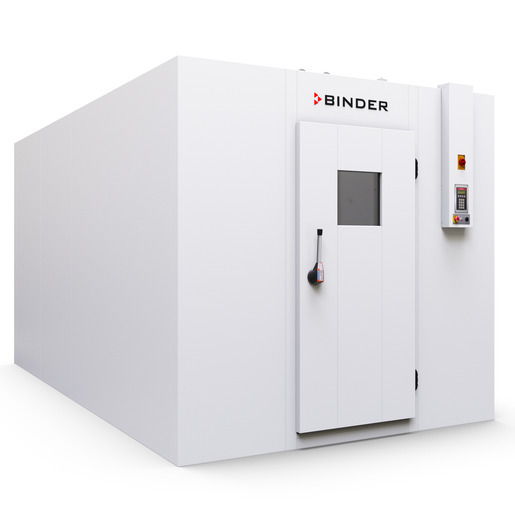
BINDER WIC 3
BINDER WIC 3 — Climate chambers.
The WIC 3 is a walk-in environmental chamber built from 100 mm PU-insulated steel panels with a separate rear-mounted conditioner, offering 24,516 L interior volume and 10.8 m² floor area. It is the largest of the WIC series (WIC 1, WIC 2, WIC 3), distinguished by three air baffles and a 2.70 kW single-phase 230 V supply. It is used for ICH Q1A stability testing and constant-climate storage of non-hazardous goods within 5–50 °C and 20–90 % r.h.
BINDER WIC Series — Model Comparison & Selection
Full specifications
| Interior volume | 24516 L |
| Nominal power | 2.7 kW |
| Temperature fluctuation | 0.5 K |
| Temperature uniformity | 1.5 K |
| Article Number mfr | 9800 |
| Depth | 4700 mm |
| Height | 2470 mm |
| Interior height | 2270 mm |
| Interior width | 2400 mm |
| Width | 2600 mm |
| Net weight of the unit (empty) mfr | 1186 kg |
| Power frequency | 50 Hz |
| Rated voltage | 230 V |
| Unit fuse | 16.0 A |
| Phase (Nominal voltage) mfr | 1 |
| Humidity fluctuation | 2.5 % RH |
| Humidity range | 20...90 % RH |
Description
Construction and series positioning
The WIC 3 (WIC3230V, Art. no. 9800-0013) is a modular walk-in chamber assembled from galvanized, polyester-coated steel panels with 100 mm PU foam insulation (U = 0.21 W/m²K). The floor overlay is 0.7 mm chrome-nickel steel 1.4301 on 15 mm multiplex, slip resistance R12. Unlike the smaller WIC 1 and WIC 2, the WIC 3 uses three air baffles for air distribution and has a net weight of 1,186 kg. The conditioner (Art. no. 6011-0228) is mounted at the rear as standard (front mounting optional). Interior volume is 24,516 L with 2,400 mm width, 2,270 mm height, and 4,700 mm depth; external dimensions are 2,600 mm wide, 2,470 mm high, and 4,700 mm deep. The chamber is supplied as a kit with a separate conditioner and requires on-site assembly (approximately 2 hours with 2 persons).
Behavior under load and in different media
The chamber operates from 5 °C to 50 °C with humidity, with a temperature fluctuation of 0.5 K and uniformity of 1.5 K. Humidity is controlled from 20 % to 90 % r.h. with a fluctuation of 2.5 % r.h. The refrigerant is R450a (0.737 kg charge, GWP 547), maximum operating pressure 17 bar. The door frame heater is independently controlled with a maximum setpoint of 55 °C and protected by a temperature limiter and two additional fuses in the conditioner. The chamber is not designed for hazardous locations; it must be installed in a dry, splash-proof area. The floor can support a surface load of 50,000 N/m² and rubber wheel load of 1,000 N/4 cm²; steel wheels are not permitted.
Installation, connection, and control
Electrical supply is 230 V, 1~, 50 Hz, 2.7 kW nominal, 16 A fuse. The junction box contains overcurrent protection and circuit breakers; connection is made to the customer's supply according to the manual. Water connections are 1/2" female NPT for fresh water inlet and waste water drain. The SmartPad controller provides setpoint entry and terminal lock. Safety features include an Emergency Off (EMO) switch and an adjustable thermal protection for the chamber interior (DIN 12880 Class 1/3.1). The chamber must be installed with minimum clearances: 500 mm rear, 100 mm side, 1.5 m door side, and ceiling height at least 2.59 m.
Integration & Operating Notes
The installation floor must withstand a surface load of 50,000 N/m² (1,000 lbs/sq. ft.) and a rubber wheel load of 1,000 N/4 cm². Steel-wheeled transport equipment must not enter the chamber. Verify structural capacity before positioning the chamber, especially for the 1,186 kg empty weight plus payload.
The chamber requires a single-phase 230 V, 50 Hz supply with a 16 A fuse. Voltage tolerance is ±10%. The junction box includes overcurrent protection and circuit breakers; the customer must provide a suitable supply cable and earth connection. Verify local frequency (50 or 60 Hz) and ensure the supply can deliver 2.7 kW continuously.
The humidification system operates with tap water via 1/2" female NPT fresh water inlet and waste water drain. Water quality must meet chap. 4.3.1. The chamber cannot achieve humidity below 20 % r.h. or above 90 % r.h. Ensure continuous water supply and proper drainage to avoid low tub water level malfunctions.
Selection & Integration Q&A
Choose WIC 3 when you need the largest usable volume (24,516 L) and floor area (10.8 m²) for high-throughput stability testing. WIC 1 (12.5 m³) and WIC 2 (18.5 m³) are smaller; WIC 3 also uses three air baffles for uniform air distribution. Select based on required capacity and site dimensions.
The conditioner requires a fresh water inlet and waste water drain, both 1/2" female NPT. Water quality must meet chap. 4.3.1. Ensure continuous supply and proper drainage to prevent low tub water level errors. Plumbing must be installed before commissioning.
Annual maintenance by licensed electrician and electrical inspection per EN 50678/50699. Accessories not included: shelf set WIC 3 (8012-2242), accessory pack (8009-1201), door sill ramp, and connection box (5001-0055). These must be ordered separately. Installation tools are also not included.