
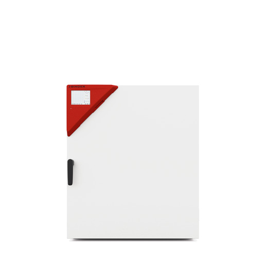
BINDER M 260
BINDER M 260 — Drying ovens with Temperature 14…300 °C.
The BINDER M 260 is a 256 L forced-convection drying and heating chamber with a +14 to 300 °C working range, 3.1 kW heating, and 65 air changes per hour. Its 400 V three-phase connection and 40 kg per-rack load capacity distinguish it from smaller single-phase siblings. It serves batch drying, heating, and thermal testing where uniform temperature and programmability are required.
BINDER M Series — Model Comparison & Selection
Full specifications
| Temperature | 14...300 °C |
| Air change rate | 65 x/h |
| Heating time to 150°C | 13 min |
| Interior volume | 256 L |
| Load per rack | 40 kg |
| Nominal power | 3.1 kW |
| Permitted load | 270 kg |
| Temperature fluctuation | 0.4 K |
| Temperature uniformity | 1.5 K |
| Rear wall clearance | 160 mm |
| Side wall clearance | 100 mm |
| Article Number mfr | 9010 |
| Recovery time after door was opened for 30 s at 150°C mfr | 6 min |
| Depth | 786 mm |
| Height | 962 mm |
| Width | 810 mm |
| Net weight of the unit (empty) mfr | 86 kg |
| Power frequency | 50 Hz |
| Rated voltage | 400 V |
| Unit fuse | 16.0 A |
| Phase (Nominal voltage) mfr | 3 N/PE |
Description
Construction and series positioning
The M 260 (E3.1) is the mid-large chamber in the M series, offering 256 L interior volume with net dimensions of 810 mm wide, 962 mm high, and 786 mm deep. Unlike the M 56 and M 115, which operate from +23 °C and use 230 V single-phase power, the M 260 starts at +14 °C and requires a 400 V 3 N/PE 50 Hz supply with a 16 A unit fuse. The M 720 shares the same temperature range and three-phase architecture but provides a larger chamber. The M 260 is equipped with the MB2 microprocessor controller and forced convection, supporting fixed-value, timer, time-program, and week-program operating modes.
Thermal behavior and load handling
Heating from ambient to 150 °C takes 13 minutes, with a temperature fluctuation of 0.4 K and uniformity of 1.5 K. After a 30-second door opening at 150 °C, the chamber recovers in 6 minutes. The permitted load is 270 kg total, with a maximum of 40 kg per rack. The air-change rate is 65 per hour, and the air flap position can be adjusted via the controller. The chamber must not be loaded with materials that are combustible or explosive at the working temperature; the set-point must remain below the flash point or sublimation point of the charge.
Installation, control, and operation
The rear panel provides a SUB-D socket for a zero-voltage relay alarm contact and an optional analog output for temperature. For sizes 260 and 720, the main power switch is located on the rear, so the installation site must allow access. The MB2 controller supports user management with password protection, Ethernet communication, USB data transfer, and an optional APT-COM 4 software for networking up to 100 chambers. The chamber includes a selectable overtemperature safety controller class 2 (temperature limiter) or class 3.1, and a class 1 protective device that trips if the temperature exceeds a factory-set limit. The chamber is IP 20 and must not be installed in damp areas or unventilated recesses; minimum wall clearances are 160 mm at the rear and 100 mm at the sides.
Integration & Operating Notes
The M 260 draws 3.1 kW from a 400 V 3 N/PE 50 Hz supply and requires a 16 A unit fuse. A single-phase 230 V supply used for smaller M models is not compatible; verify that the site provides a five-pin CEE 16/6 H plug connection and that the supply voltage stays within tolerance.
The chamber must not be installed in unventilated recesses. Prescribed minimum distances of 160 mm at the rear and 100 mm at the sides ensure heat dispersal and prevent overheating. The rear main power switch must remain accessible for disconnection during maintenance.
Do not introduce substances that are combustible or explosive at the working temperature. The temperature inside the chamber must lie below the flash point or sublimation point of the charging material. The chamber has no explosion protection measures and must not be operated in potentially explosive areas.
A SUB-D socket 'ALARM / CONTACT' on the rear provides a zero-voltage relay alarm contact that can be wired to external monitoring systems. The optional analog output for temperature is a separate SUB-D socket. Plan cabling for these signals if remote alarm or recording is required.
Maintenance must be performed at least once a year by licensed electricians or experts authorized by BINDER; otherwise the warranty becomes void. Before maintenance, disconnect the chamber and pull the power plug. Do not remove the rear panel. After maintenance, a repeat electrical inspection per EN 50678/VDE 0701 and EN 50699/VDE 0702 is required before resuming operation.
If the overtemperature protective device class 1 has turned off the chamber, disconnect it from the power supply for at least 10 seconds and let it cool down. If the device responds again, contact BINDER service. This reset procedure is defined to prevent repeated tripping without investigation.
Selection & Integration Q&A
Choose the M 260 for 256 L batches requiring +14 °C start and 400 V three-phase power. The M 115 offers only 115 L and +23 °C start on 230 V single-phase; the M 720 provides a larger chamber but same temperature range and three-phase supply. Select the M 260 when its volume and load capacity (270 kg total, 40 kg per rack) match your batch size without excess.
The M 260 requires a 400 V 3 N/PE 50 Hz supply with a 16 A unit fuse and a five-pin CEE 16/6 H plug. Nominal power is 3.1 kW. Verify that the supply voltage stays within tolerance and that the rear main power switch remains accessible. A 230 V single-phase supply is not compatible.
Install the chamber in a dry, splash-proof location with at least 160 mm rear clearance and 100 mm side clearance. Do not install in unventilated recesses or damp areas; IP 20 protection does not allow water exposure. The chamber must not be operated in potentially explosive atmospheres. The rear main power switch must remain accessible.
Annual maintenance by BINDER-authorized personnel is mandatory to preserve warranty, plus repeat electrical inspection per EN 50678/VDE 0701 and EN 50699/VDE 0702. Accessories such as APT-COM 4 software, Pt100 object temperature sensor, analog output, HEPA fresh air filter, and inert gas connection are not included and must be ordered separately. Door gasket replacement requires a cold chamber.