
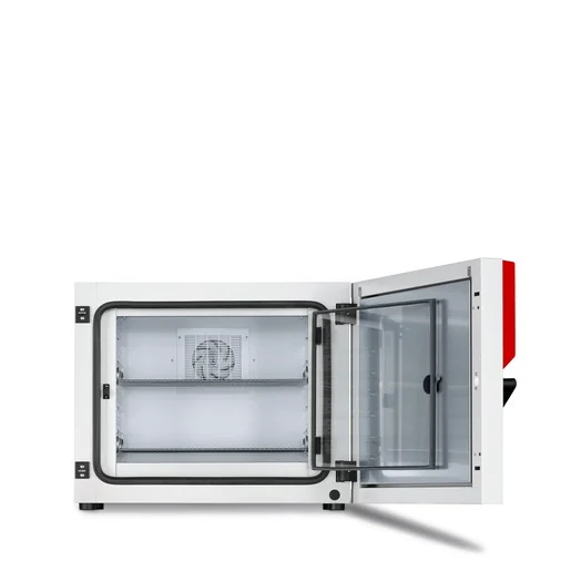
BINDER KT 115
BINDER KT 115 — Incubators with Temperature 4…100 °C.
The BINDER KT 115 is a 102 L Peltier-cooled incubator operating from 4 to 100 °C with 0.1 K fluctuation and 0.3 K uniformity. As the mid-size standard 230 V variant (KT115-230V, Art. 9020-0313) in the KT series, it sits between the KT 53 and KT 170. It is intended for refrigerated incubation, long-term storage at 4 °C, and alternating 37 °C / 4 °C protocols.
Direct drop-in replacements
BINDER KT Series — Model Comparison & Selection
Full specifications
| Temperature | 4...100 °C |
| Interior volume | 102 L |
| Load per rack | 30 kg |
| Max. heat compensation | 100 W |
| Nominal power | 0.7 kW |
| Permitted load | 100 kg (KT115-230V / KT115UL-120V) |
| Temperature fluctuation | 0.1 K |
| Temperature uniformity | 0.3 K |
| Back wall clearance | 100 mm (KT115-230V / KT115UL-120V) |
| Side wall clearance | 240 mm (KT115-230V / KT115UL-120V) |
| Article Number mfr | 9020 |
| Recovery time after door was opened for 30 s at 37°C mfr | 3 min |
| Depth | 655 mm (KT115-230V / KT115UL-120V) |
| Height | 715 mm (KT115-230V / KT115UL-120V) |
| Interior width | 600 mm (KT115-230V / KT115UL-120V) |
| Width | 860 mm (KT115-230V / KT115UL-120V) |
| Net weight of the unit (empty) mfr | 83 kg |
| Power frequency | 50 Hz |
| Rated voltage | 200...240 V |
| Unit fuse | 10.0 A |
| Phase (Nominal voltage) mfr | 1 |
Description
Construction and series positioning
- The KT 115 uses Peltier refrigerating technology with HIT insulation and the APT.line preheating chamber system; control is via the T4.12 program controller.
- Interior volume is 102 L (600 mm W × 655 mm D × 715 mm H net), with a permitted load of 100 kg and 30 kg per rack.
- Within the KT series, the KT 115 is the mid-capacity model; the KT 53 and KT 170 share the same 4...100 °C range but differ in chamber volume. This model is the standard 230 V variant (KT115-230V, Art. 9020-0313); the UL variant KT115UL-120V (Art. 9020-0314) is a separate model for North American supply.
Behavior under load and in different modes
- Temperature fluctuation is 0.1 K and uniformity 0.3 K across the working range. Recovery time after a 30 s door opening at 37 °C is 3 min.
- Maximum heat compensation is 100 W, which bounds the permissible heat load from the charging material.
- The intended application range is 4 °C to 37 °C for cultivation of microorganisms; typical uses include long-term storage at 4 °C, refrigerated incubation at 20–25 °C, incubation at 37 °C, and alternating 37 °C / 4 °C. The full 4...100 °C range is available, but operation must remain within the intended use.
- Time and week programs in the T4.12 controller support set-point ramps/steps, section repetition, tolerance ranges, and optional zero-voltage relay outputs for external switching.
Installation, connection and control
- Electrical supply: 200...240 V, 1~, 50 Hz, nominal power 0.7 kW, unit fuse 10.0 A. The 230 V model uses a CEE 7/7 plug.
- Required clearances: 100 mm at the rear and 240 mm at the side. Do not install in unventilated recesses; sufficient ventilation is required for heat dispersal.
- The T4.12 controller provides fixed-value mode, time and week programs, key lock, USB data export/import, graphical measured-value display, and an event list. Alarm states are set, acknowledged, and cleared; a door alarm delay is configurable.
- Optional equipment includes door heating, zero-voltage relay alarm/control outputs, object temperature display with flexible Pt 100 sensor, and APT-COM 4 software. These are configured in the controller menu.
Integration & Operating Notes
The chamber requires 100 mm clearance at the rear and 240 mm at the side for heat dispersal. Installing it in an unventilated recess or closer than these distances risks overheating and chamber damage, because the Peltier system rejects heat to the ambient air.
The KT115-230V is rated for 200...240 V, 1~, 50 Hz with a 10.0 A unit fuse and 0.7 kW nominal power. Supply voltage and frequency must lie within the nominal range ±10% at the indicated power frequency; otherwise the Peltier system and controller may not operate correctly.
The Peltier cooling system can compensate a maximum heat input of 100 W from the charging material. Exceeding this heat load will prevent the chamber from holding setpoint, particularly at low temperatures such as 4 °C. Size the load and its heat dissipation accordingly.
Alarm states are set (active, buzzer sounds), acknowledged (active, buzzer off, alarm icon remains), and cleared (cause disappeared). Acknowledging an alarm only silences the buzzer; the alarm remains active until the cause is remedied. Operators must not treat acknowledgment as resolution.
Maintenance must be performed at least once a year by licensed electricians or experts authorized by BINDER; warranty becomes void if maintenance is conducted by non-authorized personnel. Annual repeat electrical inspection per EN 50678/VDE 0701 and EN 50699/VDE 0702 is also required, plus a test before initial startup and before resuming operation after maintenance or repair.
With increased dust in the ambient air, clean the Peltier fan grid by suction or blowing several times a year. A clogged fan grid reduces heat rejection and cooling performance. Before any maintenance work, turn off the chamber at the main power switch and disconnect the power plug; do not remove the rear panel.
The door gasket must be replaced only when cold; otherwise the gasket may become damaged. Allow the chamber to cool before replacement. After any maintenance, the chamber must be tested before resuming operation.
The chamber is rated IP 20 according to EN 60529: protected against solid objects >12.5 mm but not water. Install it in a splash-proof manner and do not wet the chamber. The temperature safety device conforms to DIN 12880:2007 class 3.1.
Selection & Integration Q&A
Choose the KT 115 when 102 L interior volume fits the load and the 100 kg permitted load / 30 kg per rack is sufficient. The KT 53 is smaller; the KT 170 is larger. All share the 4...100 °C range and Peltier technology, so volume and load capacity are the deciding factors.
The KT115-230V requires 200...240 V, 1~, 50 Hz with a 10.0 A unit fuse and 0.7 kW nominal power, using a CEE 7/7 plug. Supply voltage and frequency must be within ±10% of nominal. For North American 100...120 V supplies, the separate KT115UL-120V model (NEMA 5-20 plug) is required.
Provide 100 mm clearance at the rear and 240 mm at the side, and do not install in unventilated recesses; sufficient ventilation is needed for heat dispersal. The chamber is IP 20 and must be installed splash-proof. In dusty air, clean the Peltier fan grid several times a year.
Annual maintenance by BINDER-authorized personnel and annual electrical repeat inspection per EN 50678/VDE 0701 and EN 50699/VDE 0702 are required. Optional items not in base delivery include door heating, zero-voltage relay alarm/control outputs, object temperature display with Pt 100 sensor, and APT-COM 4 software.