
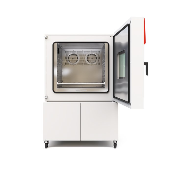
BINDER MKF 400 CO₂
BINDER MKF 400 CO₂ — Climate chambers.
The MKF 400 CO₂ is a 417 L alternating climate chamber with a working range of -50 to 180 °C and 10–98 % RH, built for 400 V/50 Hz three-phase supply. It is the mid-size CO₂-refrigerant variant of the MKF (E6) series, distinguished from the MKF 240 and MKF 1020 by its 417 L interior and 30 kg per-rack load rating. It serves cyclic temperature-humidity testing in a single programmable chamber.
BINDER MKF Series — Model Comparison & Selection
| Model | Temperature, °C | Height, cm | Interior volume, L | Load per rack, kg | Max heat compensation, W | Nominal power, kW |
|---|---|---|---|---|---|---|
| MKF 400 CO₂ Current | -50...180 | 172.7 | 417 | 30 | 1600 | 7.9 |
| MKF 1020 | -40–180 | 200.5 | 991 | 40 | 1500 | 12.5 |
| MKF 1020 CO₂ | -48–180 | 200.5 | 991 | 40 | 1400 | 11.5 |
| MKF 115 | -40–180 | 172.5 | 115 | 30 | 400 | 4.8 |
| MKF 240 | -40–180 | 171.5 | 228 | 30 | 400 | 6.8 |
| MKF 240 CO₂ | -50...180 | 171.3 | 228 | 30 | 900 | 6.8 |
| MKF 400 | -40–180 | 171 | 417 | 30 | 800 | 8 |
| MKF 56 | -40–180 | 144.5 | 60 | 15 | 250 | 2.8 |
| MKF 720 | -40–180 | 200.5 | 734 | 40 | 1000 | 11 |
| MKF 720 CO₂ | -48–180 | 200.5 | 734 | 40 | 1100 | 11 |
Full specifications
| Temperature | -50...180 |
| Interior volume | 417 L (MKF400CO2-400V / MKF400-480V) |
| Load per rack | 30 kg (MKF400CO2-400V / MKF400-480V) |
| Maximum heat compensation | 1600 W |
| Nominal power | 7.9 kW (MKF400CO2-400V / MKF400-480V) |
| Article Number mfr | 9020 |
| Depth | 1400 mm (MKF400CO2-400V / MKF400-480V) |
| Height | 1727 mm (MKF400CO2-400V / MKF400-480V) |
| Width | 1115 mm (MKF400CO2-400V / MKF400-480V) |
| Power frequency | 50 Hz (MKF400CO2-400V) |
| Rated voltage | 400 V |
| Unit fuse | 16.0 A (MKF400CO2-400V / MKF400-480V) |
| Humidity range | 10...98 % RH |
| Cooling down time from 180°C to -40°C mfr | 80 min |
| Humidity fluctuation with humidity dependent on set value mfr | 2 % r.F. |
| Average heating-up rate according to IEC 60068-3-5 between -40°C and 180°C mfr | 5.7 K/min |
Description
Construction and series positioning
- The MKF 400 CO₂ is a floor-standing alternating climate chamber with a 417 L net interior (1,400 mm depth, 1,727 mm height, 1,115 mm width) and a 30 kg per-rack load limit.
- Within the MKF (E6) series it sits between the MKF 240 and the larger MKF 720/MKF 1020; the CO₂ designation refers to the R 744 refrigerant circuit, not to a CO₂ gas control function.
- The 400 V/50 Hz variant (Art. 9020-0519) is the European-supply configuration; a 480 V/60 Hz sibling exists but is a separate article.
Thermal and humidity behavior
- Temperature range is -50 to 180 °C; with humidity active the range narrows to 10–95 °C and 10–98 % RH.
- Average heating rate is 5.7 K/min (-40 to 180 °C) and cooling rate 5.0 K/min (180 to -40 °C), with a full 180 to -40 °C cool-down taking 80 min per IEC 60068-3-5.
- Temperature uniformity is 0.1–1.0 K and fluctuation 0.1–0.4 K depending on setpoint; humidity fluctuation is 2 % r.F. and temperature fluctuation under humidity 0.1–1 K.
- Maximum heat compensation is 1,600 W, which bounds the dissipative load a test specimen may introduce.
Control, installation and operation
- The MB2 chamber controller provides fixed-value, timer, time-program and week-program modes, chart-recorder display, alarm/notification handling, user management with password levels, and USB/Ethernet/serial communication options.
- Humidity is supplied either automatically from a freshwater pipe or manually from the internal freshwater can; wastewater must be connected.
- Temperature safety is provided by an over-temperature protective device (class 1) plus a safety controller (class 2.0 per DIN 12880), with an optional class 2 over/under device.
- The chamber requires a type B residual current circuit breaker, ±10 % voltage tolerance at the indicated frequency, and installation room volume verified per EN 378-1.
Integration & Operating Notes
The chamber label and manual require operation only with residual current circuit breakers type B; a standard type A or AC RCD is not acceptable because of the CO₂ refrigeration circuit's DC/leakage characteristics. Verify the building distribution before commissioning.
The nominal voltage tolerance is ±10 % at the indicated power frequency. With a 7.9 kW nominal load and 16.0 A unit fuse, sustained deviation outside this band risks compressor and controller faults; size the feeder and upstream protection from the actual unit type plate.
Because the refrigeration circuit uses R 744 (CO₂) at up to 120 bar, the installation room volume must be calculated according to EN 378-1:2016+A1:2020. Do not install in unventilated recesses and observe the minimum distances in chapter 3.4 to disperse heat.
The humidity sensor has tabulated maximum workplace threshold and permanent-load concentrations for substances such as ammonia, acetone, ethanol, formaldehyde, ozone and sulphur dioxide. Test specimens outgassing above these limits will degrade the sensor; check the material list before loading.
With humidity active the chamber is limited to 10–95 °C and 10–98 % RH; below 10 °C or above 95 °C humidity control must be switched off. Program setpoints accordingly to avoid condensation or humidifier faults.
The over-temperature safety device class 2.0 per DIN 12880 requires its setpoint and alarm-state measures to be configured and its function checked per Section 12 before programs run. The optional class 2 over/under device adds under-temperature protection for sensitive specimens.
After 8760 operating hours or two years the controller displays a service message; after confirmation it reappears every two weeks until reset by BINDER Service. Plan the annual maintenance and the BINDER reset together to avoid recurring interruptions.
Repairs to the CO₂ refrigeration circuit may currently only be carried out at BINDER, and all refrigeration work must be documented in a service log book by personnel trained per EN 13313:2010. Condensers should be cleaned every 1–2 years and the steam humidifier at least annually, with frequency set by water quality.
Selection & Integration Q&A
Pick the 400 when 417 L and 30 kg per rack fit your specimen batch; the 240 is smaller, the 1020 larger. The CO₂ designation is the refrigerant, not a gas function, so all MKF variants share the same humidity principle.
3 N/PE 400 V 50 Hz, 7.9 kW nominal, 16.0 A unit fuse, voltage within ±10 %, and a type B RCD. Size the feeder from the actual unit type plate, since nominal current can differ from the catalogue value.
Provide a freshwater pipe connection kit or fill the internal can manually, plus a wastewater drain. The room volume must satisfy EN 378-1, with ventilation and minimum clearances per chapter 3.4; unventilated recesses are prohibited.
Annual maintenance, condenser cleaning every 1–2 years and yearly steam-humidifier service are user-scheduled; the RS485 interface, analog outputs, Pt 100 object sensor, safety kit and APT-COM 4 are options. The two-year/8760-hour service message needs a BINDER reset.