BINDER MKF 240
BINDER MKF 240 — Climate chambers with Temperature -40…180 °C.
The MKF 240 is a 228 L alternating climate chamber with a working range of -40…180 °C and 10…98 % RH, built for rapid temperature cycling (5 K/min heating, 120 min from 180 °C to -40 °C). It is the mid-size 400 V model in the MKF series, distinguished from the CO₂ variants by its standard humidity system and from smaller siblings by its 30 kg-per-rack load capacity.
BINDER MKF Series — Model Comparison & Selection
| Model | Temperature, °C | Height, cm | Interior volume, L | Load per rack, kg | Max heat compensation, W | Nominal power, kW |
|---|---|---|---|---|---|---|
| MKF 240 Current | -40–180 | 171.5 | 228 | 30 | 400 | 6.8 |
| MKF 1020 | -40–180 | 200.5 | 991 | 40 | 1500 | 12.5 |
| MKF 1020 CO₂ | -48–180 | 200.5 | 991 | 40 | 1400 | 11.5 |
| MKF 115 | -40–180 | 172.5 | 115 | 30 | 400 | 4.8 |
| MKF 240 CO₂ | -50...180 | 171.3 | 228 | 30 | 900 | 6.8 |
| MKF 400 | -40–180 | 171 | 417 | 30 | 800 | 8 |
| MKF 400 CO₂ | -50...180 | 172.7 | 417 | 30 | 1600 | 7.9 |
| MKF 56 | -40–180 | 144.5 | 60 | 15 | 250 | 2.8 |
| MKF 720 | -40–180 | 200.5 | 734 | 40 | 1000 | 11 |
| MKF 720 CO₂ | -48–180 | 200.5 | 734 | 40 | 1100 | 11 |
Full specifications
| Temperature | -40...180 °C |
| Interior volume | 228 L (MKF240-400V, 50 Hz) |
| Load per rack | 30 kg (MKF240-400V, 50 Hz) |
| Maximum heat compensation | 400 W |
| Nominal power | 6.8 kW (MKF240-400V, 50 Hz) |
| Article Number mfr | 9020 |
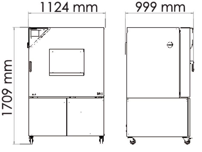
| Height | 1715 mm (MKF240-400V, 50 Hz) |
| Width | 1115 mm (MKF240-400V, 50 Hz) |
| Power frequency | 50 Hz (MKF240-400V) |
| Rated voltage | 400 V |
| Unit fuse | 16.0 A (MKF240-400V, 50 Hz) |
| Humidity range | 10...98 % RH |
| Cooling down time from 180°C to -40°C mfr | 120 min |
| Humidity fluctuation with humidity dependent on set value mfr | 2.5 % r.F. |
| Average heating-up rate according to IEC 60068-3-5 between -40°C and 180°C mfr | 5.0 K/min |
Description
Construction and series positioning
- The MKF 240 uses the MKF (E5) platform with HIT Insulation® and program control; it is the 240-size model between the MKF 115 and MKF 400.
- Unlike the MKF 240 CO₂ sibling, this model does not extend the low-temperature limit to -50 °C; its range is -40…180 °C.
- The standard variant is MKF240-400V (400 V 3~/N/PE 50 Hz, Art. No. 9020-0380); the -C variant (MKF240-400V-C) adds a voltage and frequency changer for 60 Hz / 480 V supplies.
- Interior volume is 228 L; net width 1,115 mm and net height 1,715 mm.
Behavior under load and in different media
- Temperature uniformity is 0.1…1.5 K and fluctuation 0.1…0.5 K, both dependent on set value; with humidity active, the temperature range narrows to 10…95 °C and fluctuation rises to 0.1…1.3 K.
- Humidity fluctuation is 2.5 % r.F.; the humidity system uses freshwater and wastewater paths, with a water circle lever for condensate recycling available from size 115 on.
- Maximum heat compensation is 400 W, which defines the permissible load dissipation inside the chamber; load per rack is limited to 30 kg.
- Defrosting during refrigerating operation and anti-condensation protection are handled by the controller.
Installation, connection and control
- Electrical supply is 400 V 3 N/PE 50 Hz with a 16.0 A unit fuse and 6.8 kW nominal power; the rear power switch (present from size 115 on) must be on in addition to the main power switch.
- Water connections include freshwater supply (automatic via pipe or manual via internal freshwater can from size 115 on) and wastewater; the water cooling option requires cooling water inlet/outlet.
- The MB2 chamber controller supports fixed-value, timer, time-program and week-program modes, with alarm/notification functions, user management and a chart-recorder display.
- Temperature safety devices include over-temperature protection class 1 and a safety controller class 2; an optional over/under temperature safety device class 2 is available.
Integration & Operating Notes
The chamber draws 6.8 kW nominal at 400 V 3 N/PE 50 Hz and requires a 16.0 A unit fuse. Verify that the site supply and upstream protection match these values before connection; the -C variant is required for 480 V 60 Hz networks.
From size 115 on, the chamber has a rear power switch in addition to the main power switch. Both must be on for commissioning and troubleshooting, so leave sufficient clearance behind the unit for access.
With humidity active, the temperature range is limited to 10…95 °C and temperature fluctuation increases to 0.1…1.3 K. Plan test profiles that require humidity within this band; outside it, only dry operation is possible.
The maximum heat compensation is 400 W. Exceeding this load dissipation can prevent the chamber from holding setpoint. Calculate the total power dissipated by test specimens and keep it below this limit.
Regular maintenance at least once a year and a leak test per Regulation (EU) 517/2014 are mandatory. Schedule these and document them in the service log book; also plan humidifier maintenance annually, depending on water quality.
After 8760 operating hours or two years, a service message appears; after confirmation it reappears every two weeks until reset by BINDER Service. Plan a BINDER Service intervention to reset it and avoid repeated alarms.
The humidification system uses freshwater and wastewater paths. Water quality affects humidifier maintenance intervals; verify that the site water supply meets the chamber's requirements and that wastewater drainage is available.
The controller provides zero-voltage switching outputs for external switching or signaling. Use these to interlock ancillary devices or alarms; they do not supply power, so an external relay or contactor is required.
Selection & Integration Q&A
Choose the MKF 240 for standard alternating climate testing from -40 to 180 °C with humidity; the CO₂ variant extends the low end to -50 °C. The MKF 115 offers less interior volume (115 L) and lower load capacity, so select the 240 when 228 L and 30 kg per rack are needed.
Annual maintenance and a leak test per EU 517/2014 are mandatory; humidifier maintenance is annual, and condensers should be cleaned every 1–2 years. Options not included: water cooling, compressed air dryer, RS485 interface, analog outputs, Pt 100 sensor, APT-COM™ software, and external freshwater/wastewater cans (MKF 56 only).
In dusty ambient air, check the condenser fan grid behind the left maintenance access flap weekly and clean by suction after disconnecting the chamber. The chamber is not rated for continuous condensing operation; defrosting cycles are required during refrigerating operation.