
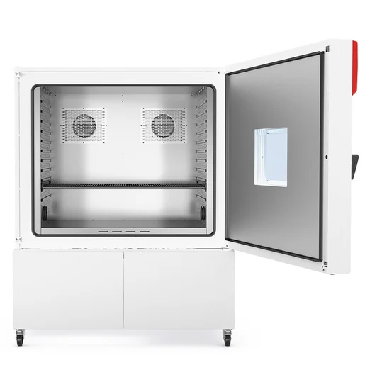
BINDER MKF 1020
BINDER MKF 1020 — Climate chambers with Temperature -40…180 °C.
The BINDER MKF 1020 is a 991 L alternating climate chamber with a working range of -40 to +180 °C and 10–98 % RH, designed for rapid temperature cycling at up to 5.5 K/min heating and 5.0 K/min cooling. Its 12.5 kW heating and 1.5 kW heat compensation at 400 V 3 N/PE 50 Hz distinguish it as the largest standard 400 V model in the MKF series, excluding the CO₂ variant. It is used for reproducible climatic testing of large components and batch loads in laboratory and industrial qualification processes.
BINDER MKF Series — Model Comparison & Selection
| Model | Temperature, °C | Height, cm | Interior volume, L | Load per rack, kg | Max heat compensation, W | Nominal power, kW |
|---|---|---|---|---|---|---|
| MKF 1020 Current | -40–180 | 200.5 | 991 | 40 | 1500 | 12.5 |
| MKF 1020 CO₂ | -48–180 | 200.5 | 991 | 40 | 1400 | 11.5 |
| MKF 115 | -40–180 | 172.5 | 115 | 30 | 400 | 4.8 |
| MKF 240 | -40–180 | 171.5 | 228 | 30 | 400 | 6.8 |
| MKF 240 CO₂ | -50...180 | 171.3 | 228 | 30 | 900 | 6.8 |
| MKF 400 | -40–180 | 171 | 417 | 30 | 800 | 8 |
| MKF 400 CO₂ | -50...180 | 172.7 | 417 | 30 | 1600 | 7.9 |
| MKF 56 | -40–180 | 144.5 | 60 | 15 | 250 | 2.8 |
| MKF 720 | -40–180 | 200.5 | 734 | 40 | 1000 | 11 |
| MKF 720 CO₂ | -48–180 | 200.5 | 734 | 40 | 1100 | 11 |
Full specifications
| Temperature | -40...180 °C |
| Interior volume | 991 L (MKF1020-400V, 50 Hz) |
| Load per rack | 40 kg (MKF1020-400V, 50 Hz) |
| Maximum heat compensation | 1500 W |
| Nominal power | 12.5 kW (MKF1020-400V, 50 Hz) |
| Article Number mfr | 9020 |
| Depth | 1480 mm (MKF1020-400V, 50 Hz) |
| Height | 2005 mm (MKF1020-400V, 50 Hz) |
| Interior height | 1020 mm (MKF1020-400V, 50 Hz) |
| Interior width | 1200 mm (MKF1020-400V, 50 Hz) |
| Width | 1580 mm (MKF1020-400V, 50 Hz) |
| Power frequency | 50 Hz |
| Rated voltage | 400 V |
| Unit fuse | 32.0 A (MKF1020-400V, 50 Hz) |
| Humidity range | 10...98 % RH |
| Cooling down time from 180°C to -40°C mfr | 120 min |
| Humidity fluctuation with humidity dependent on set value mfr | 2.5 % r.F. |
| Average heating-up rate according to IEC 60068-3-5 between -40°C and 180°C mfr | 5.5 K/min |
Description
Construction and series positioning
- The MKF 1020 is the largest standard 400 V model in the MKF series, with 991 L interior volume (1200 × 1020 × 1480 mm W×H×D) and a 1580 mm wide cabinet.
- Unlike the MKF 1020 CO₂ sibling, which extends down to -48 °C, this model covers -40 to +180 °C; it shares that range with the smaller MKF 115 and MKF 240 but offers roughly 4× the volume of the MKF 240.
- The chamber is equipped with a rear power switch (standard from size 115 upward) in addition to the main power switch, and uses the MB2 chamber controller with program and fixed-value modes.
Behavior under load and in different media
- Temperature uniformity is 0.1–1.8 K and fluctuation 0.1–0.5 K depending on set value; with humidity active, fluctuation is 0.1–1.5 K and humidity fluctuation 2.5 % r.F.
- Average heating from -40 to +180 °C is 5.5 K/min and cooling from +180 to -40 °C is 5.0 K/min (IEC 60068-3-5); a full cool-down from 180 to -40 °C takes 120 min.
- Maximum heat compensation is 1500 W, allowing the chamber to hold set points against heat dissipated by active test specimens.
- Humidity control spans 10–98 % RH via a steam humidifier and dehumidification system; the humidity sensor is sensitive to ammonia (max. 20 ppm workplace threshold) and ozone (0.1 ppm), so process atmospheres must be checked against the manual limits.
Installation, connection and control
- Electrical supply is 400 V 3 N/PE 50 Hz with a nominal power of 12.5 kW and a 32 A unit fuse; a voltage and frequency changer version (MKF1020-480V-C) exists for 480 V 3~ 60 Hz.
- Water connections include freshwater supply (automatic via pipe or manual via internal can from size 115 on) and wastewater; the water circle lever for condensate recycling is available as an option.
- The MB2 controller supports fixed-value, time-program and week-program operation, with ramp/step set-point entry, tolerance ranges, section repetition, alarm and notification functions, and user management with password protection.
- Temperature safety devices include an over-temperature protective device (class 1) and a safety controller (class 2) with adjustable modes; an optional over/under temperature safety device class 2 is available.
- The chamber can be integrated via RS485, Ethernet, USB, analog outputs, and zero-voltage switching outputs for external signaling.
Integration & Operating Notes
The 12.5 kW nominal power demands a dedicated three-phase supply with neutral and earth; the unit fuse rating is 32 A. Verify that the building supply and cabling can sustain this load continuously, and include the chamber in the annual electrical safety inspection per EN 50678/VDE 0701 and EN 50699/VDE 0702.
Humidity control requires a freshwater connection (automatic via pipe or manual via internal can from size 115 on) and a wastewater drain. If the water cooling option is ordered, cooling water inlet and outlet must also be provided. Ensure the water circle lever for condensate recycling is configured if required.
From size 115 upward, the chamber has a rear power switch in addition to the main power switch. During commissioning and troubleshooting, confirm that both switches are in the on position; otherwise the chamber will not power up even if the main switch is on.
The humidity sensor has resistance limits including ammonia (max. 20 ppm workplace threshold, permanent load 5500 ppm) and ozone (0.1 ppm). Process atmospheres or cleaning agents releasing these substances must be kept below the listed concentrations to avoid sensor degradation and invalid humidity readings.
Regular maintenance is required at least once a year, including a leak test per Regulation (EU) 517/2014. The steam humidifier must also be serviced annually, with intervals depending on water quality and steam output. Document all service in the log book.
After 8760 operating hours or two years, a service message appears; after confirmation it reappears every two weeks until reset by BINDER Service. Plan a service intervention at this interval to avoid recurring alarms and to maintain warranty compliance.
The door gasket must be replaced only when the chamber is cold. Attempting replacement at elevated temperatures can damage the gasket and impair sealing, leading to humidity and temperature control errors.
Selection & Integration Q&A
Choose the MKF 1020 for large-volume testing (991 L) down to -40 °C with humidity. The MKF 1020 CO₂ extends to -48 °C but is otherwise similar; smaller MKF 115/240 suit lower throughput. Select the CO₂ only if lower temperatures are essential.
It requires 400 V 3 N/PE 50 Hz, 12.5 kW, 32 A fuse. For 480 V 60 Hz sites, specify the MKF1020-480V-C with voltage/frequency changer. Integration is via RS485, Ethernet, USB, analog outputs, and zero-voltage switching outputs on the MB2 controller.
Annual maintenance and leak test are mandatory; steam humidifier serviced annually; condenser cleaned every 1–2 years. Base delivery excludes the water cooling option, water circle lever, compressed air dryer, RS485 interface, analog outputs, and APT-COM™ software. These must be ordered separately.