BINDER MKF 720
BINDER MKF 720 — Climate chambers with Temperature -40…180 °C.
The BINDER MKF 720 is a 734 L alternating climate chamber with a -40…180 °C range and 10…98 %RH humidity control, driven by an 11 kW refrigeration system. It is the mid-large 400 V standard variant (MKF720-400V, Art. 9020-0381) in the MKF series, distinguished from the -C version by its fixed 50 Hz supply. It serves cyclic temperature-humidity testing of large loads up to 40 kg per rack, with 1,000 W heat compensation at setpoint.
BINDER MKF Series — Model Comparison & Selection
| Model | Temperature, °C | Height, cm | Interior volume, L | Load per rack, kg | Max heat compensation, W | Nominal power, kW |
|---|---|---|---|---|---|---|
| MKF 720 Current | -40–180 | 200.5 | 734 | 40 | 1000 | 11 |
| MKF 1020 | -40–180 | 200.5 | 991 | 40 | 1500 | 12.5 |
| MKF 1020 CO₂ | -48–180 | 200.5 | 991 | 40 | 1400 | 11.5 |
| MKF 115 | -40–180 | 172.5 | 115 | 30 | 400 | 4.8 |
| MKF 240 | -40–180 | 171.5 | 228 | 30 | 400 | 6.8 |
| MKF 240 CO₂ | -50...180 | 171.3 | 228 | 30 | 900 | 6.8 |
| MKF 400 | -40–180 | 171 | 417 | 30 | 800 | 8 |
| MKF 400 CO₂ | -50...180 | 172.7 | 417 | 30 | 1600 | 7.9 |
| MKF 56 | -40–180 | 144.5 | 60 | 15 | 250 | 2.8 |
| MKF 720 CO₂ | -48–180 | 200.5 | 734 | 40 | 1100 | 11 |
Full specifications
| Temperature | -40...180 °C |
| Interior volume | 734 L (MKF720-400V and MKF720-480V-C) |
| Load per rack | 40 kg (MKF720-400V and MKF720-480V-C) |
| Maximum heat compensation | 1000 W |
| Nominal power | 11 kW (MKF720-400V and MKF720-480V-C) |
| Article Number mfr | 9020 |
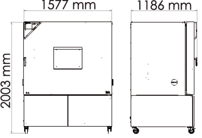
| Height | 2005 mm (MKF720-400V and MKF720-480V-C) |
| Width | 1580 mm (MKF720-400V and MKF720-480V-C) |
| Power frequency | 50 Hz (MKF720-400V) |
| Rated voltage | 400 V |
| Unit fuse | 32.0 A (MKF720-400V and MKF720-480V-C) |
| Humidity range | 10...98 % RH |
| Cooling down time from 180°C to -40°C mfr | 120 min |
| Humidity fluctuation with humidity dependent on set value mfr | 2.5 % r.F. |
| Average heating-up rate according to IEC 60068-3-5 between -40°C and 180°C mfr | 4.8 K/min |
Description
Construction and series positioning
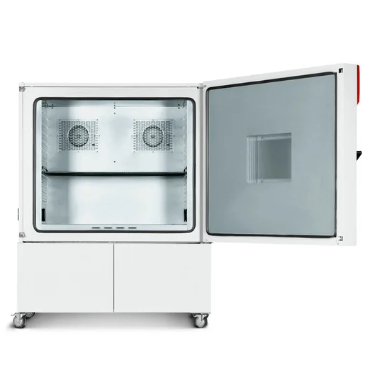
- The MKF 720 is a floor-standing alternating climate chamber with 734 L interior volume, 1,580 mm net width and 2,005 mm net height, built for program-controlled temperature and humidity cycling.
- Within the MKF series it sits between the 400 L and 1020 L sizes; the 1020 offers more volume, while the 115 and 240 are smaller. The MKF 1020 CO₂ variant extends the range to -48 °C, which the 720 does not.
- This model is the standard 400 V 3 N/PE 50 Hz version (MKF720-400V, Art. 9020-0381). The -C version (MKF720-480V-C, Art. 9020-0359) adds a voltage and frequency changer for 480 V 3~ 60 Hz supplies; choose the standard model only where 400 V 50 Hz is available.
- The chamber uses HIT Insulation® and the MB2 program controller, with a rear power switch in addition to the main switch (sizes 115 and above).
Thermal and humidity behavior
- Temperature range is -40…180 °C; with humidity active the range narrows to 10…95 °C, and humidity spans 10…98 %RH.
- Average heating and cooling rates are 4.8 K/min between -40 °C and 180 °C per IEC 60068-3-5; a full 180 °C to -40 °C cooldown takes 120 min.
- Temperature uniformity is 0.1…1.8 K and fluctuation 0.1…0.5 K depending on setpoint; with humidity, fluctuation is 0.2…1.5 K and humidity fluctuation 2.5 %r.F.
- Maximum heat compensation is 1,000 W, so live loads dissipating up to this value can be held at setpoint; loads above this will pull the chamber off setpoint.
- The steam humidifier and dehumidification system use freshwater and wastewater paths; the water circle lever for condensate recycling is available from size 115 on.
Installation, control and operation
- Electrical supply is 400 V 3 N/PE 50 Hz with 11 kW nominal power and a 32.0 A unit fuse; the rear power switch must be on for operation.
- The MB2 controller supports fixed-value, time-program and week-program modes, with ramp/step setpoints, tolerance ranges, section repetition, chart-recorder display, event list and user management with password levels.
- Temperature safety devices include an over-temperature protective device class 1 and a safety controller class 2 (optional over/under class 2). Zero-voltage switching outputs are available for external signaling.
- Water connections: freshwater supply is automatic via water pipe or manual via internal freshwater can from size 115 on; cooling water inlet/outlet only if the water cooling option is ordered. A connection kit and hose burst protection kit are available.
- Options include APT-COM™ 4 software, RS485, analog outputs, Pt 100 object sensor, compressed air connection and controlled compressed air dryer, water cooling, and BINDER Pure Aqua Service.
Integration & Operating Notes
The 11 kW nominal load and 32.0 A unit fuse require a dedicated three-phase supply with neutral and PE; the standard model has no voltage/frequency changer, so a 480 V 60 Hz site needs the -C variant instead. Verify upstream protection and cable sizing against the 32 A fuse before connection.
Maximum heat compensation is 1,000 W; a test specimen dissipating more than this will prevent the chamber from holding low setpoints and may cause sustained deviation. Calculate specimen power before programming low-temperature or humidity profiles, and consider reducing load or duty cycle.
Although the chamber reaches -40…180 °C dry, humidity operation is restricted to 10…95 °C and 10…98 %RH. Programs combining humidity with temperatures outside this window will not control RH; sequence such steps as dry phases or accept that humidity is inactive.
The humidity sensor tolerates ammonia up to 20 ppm workplace threshold (permanent 5500 ppm) and ozone up to 0.1 ppm (permanent 0.5 ppm). Process atmospheres or cleaning agents releasing these species above the limits will degrade or destroy the sensor; verify specimen outgassing before humidity testing.
From size 115 on, the chamber has a rear power switch as well as the main power switch; both must be on for commissioning and troubleshooting. Account for rear access clearance when positioning the 1,580 mm wide cabinet so the switch and water connections remain reachable.
The water cooling option is available for the MKF 720 and needs cooling water inlet and outlet connections plus a connection kit and hose burst protection kit. Without it, heat is rejected to ambient air, so room ventilation and condenser airflow must be adequate; plan plumbing before installation if water cooling is specified.
Schedule maintenance at least once a year, including the leak test per Regulation (EU) 517/2014, steam humidifier service (interval depends on water quality and steam output), and condenser cleaning every 1–2 years. Document the leak test in the service log book; electrical safety testing per EN 50678/VDE 0701 and EN 50699/VDE 0702 is recommended before first start and after repair.
After 8760 operating hours or two years the controller displays a service message; once acknowledged it reappears every two weeks until reset by BINDER Service. Plan the service intervention before the message appears to avoid repeated alarms during long test programs.
With increased dust in ambient air, inspect the fan grid behind the left maintenance access flap every week and clean by suction after disconnecting the chamber. Blocked airflow reduces cooling capacity and can trip high-temperature alarms; in clean rooms the interval can be extended.
The door gasket must be replaced only when cold; attempting replacement at elevated temperature can deform or damage the new gasket and compromise sealing. Allow the chamber to cool to ambient before service.
The chamber provides zero-voltage switching outputs for external switching or signaling, allowing alarm and state signals to be wired to a supervisory system. Use these contacts rather than switching the main load; define the fail-safe state in the integration design.
After chemical disinfection with the recommended spray (Art. No. 1002-0022), the chamber must be absolutely dry and ventilated before start-up because explosive gases may form. Other disinfectants are excluded from BINDER liability and may corrode the interior.
Selection & Integration Q&A
Choose the standard MKF720-400V (Art. 9020-0381) when your site has 400 V 3 N/PE 50 Hz; the -C version (Art. 9020-0359) adds a voltage/frequency changer for 480 V 60 Hz. Move to the MKF 1020 only if 734 L is insufficient; the 1020 CO₂ variant is needed for -48 °C, which the 720 does not reach.
The standard model requires 400 V 3 N/PE 50 Hz, 11 kW nominal, with a 32.0 A unit fuse. It cannot be connected to 480 V 60 Hz; for that supply specify the MKF720-480V-C with integrated voltage and frequency changer. Provide a dedicated circuit and verify upstream protection against the 32 A fuse.
Allow rear access for the rear power switch and water connections; the cabinet is 1,580 mm wide and 2,005 mm high. Keep ambient dust low or inspect the condenser fan grid weekly. Live loads must not exceed 1,000 W heat compensation, and humidity control is limited to 10…95 °C chamber temperature.
Plan annual maintenance with leak test per EU 517/2014, yearly steam humidifier service, condenser cleaning every 1–2 years, and electrical safety testing per EN 50678/50699. The 8760-hour service message needs BINDER reset. Options not included: water cooling plumbing, compressed air dryer, APT-COM™ 4 software, RS485, analog outputs, Pt 100 sensor, and disinfectant Art. 1002-0022.