
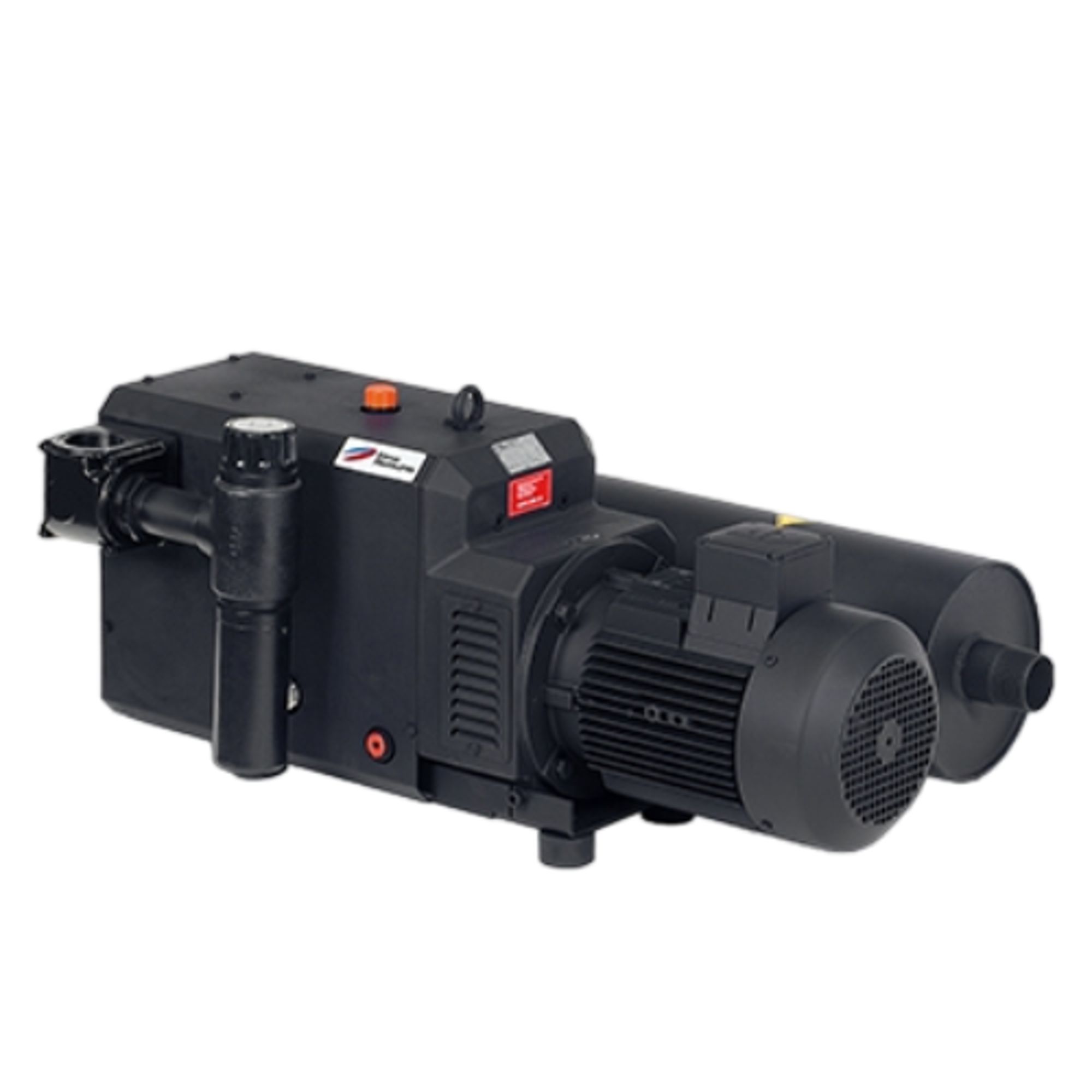
Elmo Rietschle C-VLR 150
Elmo Rietschle C-VLR 150 — Claw Vacuum Pumps.
The C-VLR 150 is a dry-running, contact-free claw vacuum pump with a double-shaft rotary piston design, driven by an integrated motor via an elastomer coupling. It delivers 150 m³/h suction capacity at 50 Hz and supports continuous operation down to 100 mbar (abs.), distinguishing it from the higher-capacity C-VLR 251 and the larger C-VLR 301/401/1000 siblings. It is intended for continuous vacuum generation in dry, non-aggressive gas processes where oil-free compression is required.
Elmo Rietschle C-VLR Series — Model Comparison & Selection
| Model | Operating principle | Noise level, dB | Weight, kg | Motor power, kW | Pumping speed, m³/h | Ultimate pressure, mbar |
|---|---|---|---|---|---|---|
| C-VLR 150 Current | Claw | — | — | — | — | — |
| C-VLR 1000 | claw | 82 | 757 | 18.5 | 950 | 200 |
| C-VLR 301 | claw | 74 | 285 | 5.5 | 290 | 150 |
| C-VLR 401 | contact free running cla | 79 | 470 | — | — | — |
| C-VLR 60 | — | 78 | 47 | — | — | — |
| C-VLR 62 | — | — | — | — | — | — |
Full specifications
| Operating principle | Claw |
| Operating temperature | 5 °C |
| Ambient temperature limit | 40 °C |
Description
Construction and series positioning
The C-VLR 150 is a double-shaft rotary piston vacuum pump with contact-free, dry-running claw rotors synchronised by an oil-lubricated gear pair. The compression chamber is separated from the gear chamber by special seals, ensuring no lubricant enters the process gas. The pump and motor form a single ready-to-connect unit, with drive transmitted via an elastomer coupling. Within the C-VLR series, the C-VLR 150 sits between the smaller C-VLR 60 and the higher-capacity C-VLR 251/301; it is the base model for 150 m³/h class duty, while the C-VLR 251 offers 215 m³/h and the C-VLR 301/401/1000 cover larger flows. The standard CD version handles dry, non-aggressive gases; the XD variant with corrosion-protective coating is available for humid or corrosive gases.
Operating behaviour and limits
The pump can run continuously at any inlet pressure between atmosphere and its specified minimum. For the C-VLR 150, continuous operation is possible down to 100 mbar (abs.), with lower pressures achievable only intermittently. Suction capacity with unrestricted suction is 150 m³/h at 50 Hz. The maximum permissible back pressure is +30 mbar; exhaust lines must be sized to avoid exceeding this. Ambient and inlet temperatures must remain between 5 °C and 40 °C. Frequent switching (around 12 times/h) at elevated temperatures may exceed motor winding and bearing temperature limits, requiring consultation with the manufacturer.
Installation, connection and control
Installation must be horizontal with a maximum inclination of 8° in all directions. Cooling air inlets and outlets require at least 30 cm clearance from walls, and at least 40 cm free space is needed before the intake silencer for maintenance. The electrical connection must be made by a qualified electrician according to EN 60204, with a user-supplied motor protection switch and main switch. Motors comply with DIN EN 60034, IP 55 and insulation class F; voltage deviation must not exceed ±5 % and frequency deviation ±2 %. Rotation direction must be checked briefly (max. 2 s) and must be counter-clockwise when viewing the motor blower. The standard vacuum control and relief valve must remain installed; operation without it is forbidden. For suction lines longer than 3 m, a non-return valve (ZRK accessory) is recommended to prevent reverse rotation after shutdown.
Integration & Operating Notes
The maximum permissible back pressure is +30 mbar. Exhaust lines must be sized and routed to avoid exceeding this limit, and no blocking devices (e.g., shut-off valves) may be installed in the exhaust line. Exceeding this limit can damage the pump or cause process instability.
The machine must be installed horizontally with a maximum inclination of 8° in all directions. The mounting surface must be plane and even, and the machine must be secured against tipping and falling. Cooling air inlets and outlets must be at least 30 cm from adjacent walls, and at least 40 cm free space is required before the intake silencer for maintenance access.
A motor protection switch with overload-dependent turn-off delay must be used to prevent nuisance tripping during cold starts, in accordance with VDE 0660 Part 102 or IEC 60947-4-1. The main switch and motor protection switch are to be provided by the user. Electrical connection must be performed by a qualified electrician per EN 60204.
Check rotation direction by briefly starting the motor for no more than two seconds. When viewing the motor blower, rotation must be counter-clockwise. Wrong rotation direction can damage the machine and cause injury. Use a phase sequence indicator if necessary.
Operation outside the 5–40 °C range requires consultation with the manufacturer; otherwise overheating or damage may occur. This applies to both ambient and inlet gas temperatures. Ensure the installation room is adequately ventilated and that exhausted cooling air is not re-sucked.
Before shutdown for more than 2 hours or decommissioning, run the pump at 700 mbar (abs.) for at least 15–30 minutes with dry air. This removes moisture and pollution to prevent deposits and start-up problems. Also drain condensate regularly during operation.
Long connecting lines of more than 3 m can cause reverse rotation after the machine is switched off. Install a non-return valve (ZRK accessory) to protect the machine. Additionally, keep suction lines as short as possible and use compensators to avoid pipe forces acting on the pump housing.
Selection & Integration Q&A
Choose the C-VLR 150 when your required suction capacity is up to 150 m³/h at 50 Hz and continuous inlet pressure is not below 100 mbar (abs.). For higher flows (215 m³/h for C-VLR 251) or deeper continuous vacuum, select the larger model.
The motor complies with DIN EN 60034, IP 55, insulation class F. Supply voltage deviation must not exceed ±5 % and frequency deviation ±2 %. A user-supplied motor protection switch with overload-dependent delay (VDE 0660 Part 102 or IEC 60947-4-1) and a main switch are required. Connection must be by a qualified electrician per EN 60204.
Install horizontally with maximum inclination 8° in all directions. Ambient and inlet temperature must be 5–40 °C. Cooling air inlets/outlets need at least 30 cm clearance from walls, and 40 cm free space before the intake silencer. For altitudes above 1000 m, output reduction occurs and the manufacturer should be consulted.
The base delivery does not include a motor protection switch, main switch, or non-return valve (ZRK accessory) for suction lines >3 m. The standard vacuum control and relief valve is part of the base delivery and must remain installed; operation without it is forbidden. Maintenance requires oil changes per schedule, intake filter and filter mesh inspection/cleaning, and coupling check. Repairs must use original spare parts.