
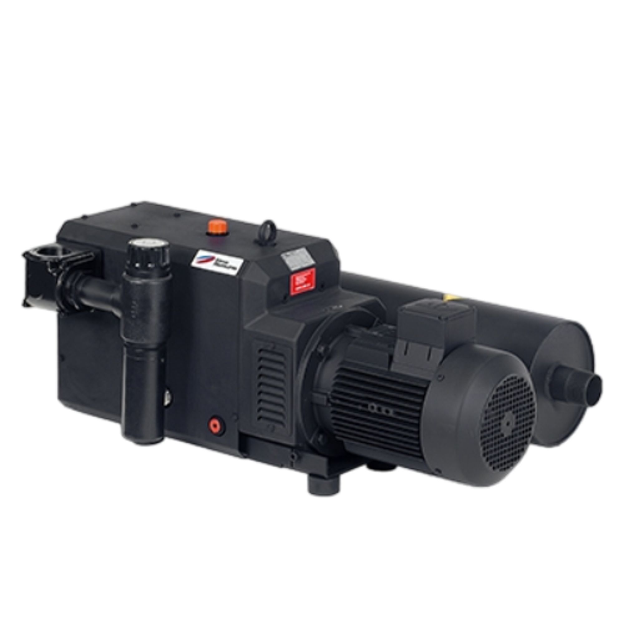
Elmo Rietschle C-VLR 60
Elmo Rietschle C-VLR 60 — Claw Vacuum Pumps.
The C-VLR 60 is a two-shaft, dry-running rotary claw vacuum pump with non-contacting rotors synchronized by an oil-lubricated gear pair, supplied as a ready-to-connect pump/motor unit. It is the smallest model in the C-VLR series, approved for continuous operation in three defined duty ranges: evacuation of closed vessels up to 1.2 m³, compression from 100 ± 20 mbar to 300 ± 50 mbar (abs.), and compression from 300 mbar to 1 bar (abs.) up to 1.05 bar (abs.). Its G 1 suction and discharge connections and 47 kg mass suit compact, horizontally mounted installations in dry vacuum and low-pressure compression processes.
Elmo Rietschle C-VLR Series — Model Comparison & Selection
| Model | Operating principle | Noise level, dB | Weight, kg | Motor power, kW | Pumping speed, m³/h | Ultimate pressure, mbar |
|---|---|---|---|---|---|---|
| C-VLR 60 Current | — | 78 | 47 | — | — | — |
| C-VLR 1000 | claw | 82 | 757 | 18.5 | 950 | 200 |
| C-VLR 150 | Claw | — | — | — | — | — |
| C-VLR 301 | claw | 74 | 285 | 5.5 | 290 | 150 |
| C-VLR 401 | contact free running cla | 79 | 470 | — | — | — |
| C-VLR 62 | — | — | — | — | — | — |
Full specifications
| Öleinfüllmenge (alt var) mfr | 0.4 l |
| Height | 295 mm |
| Length | 625 mm |
| Weight | 47 kg |
| Width | 210 mm |
| Inlet flange | G 1 |
| Outlet flange | G 1 |
| Oil capacity | 0.4 l |
| Noise level | 78 dB 50 Hz: 78 dB(A) · 60 Hz: 80 dB(A) |
| Schalldruckpegel (max.) 60 Hz (alt var) mfr | 80 dB |
Description
Construction and series positioning
- Two-shaft claw principle with non-contacting, dry-running rotors; timing is maintained by a gear pair running in an oil-filled gearbox that also lubricates the motor-side bearings.
- The pumping chamber is free of sealing and lubricating media; only the gearbox contains oil (0.4 l fill).
- A separately driven external fan supplies cooling air; housing, rotors, cover and flanges are coated for corrosion resistance.
- Within the C-VLR series, the C-VLR 60 is the smallest unit; larger siblings such as the C-VLR 150, 301, 401 and 1000 cover higher pumping speeds and motor powers (e.g. C-VLR 301: 5.5 kW, 350 m³/h, 150 mbar ultimate). The C-VLR 60 is therefore the choice for low-flow duties where the footprint and 47 kg weight matter.
Behavior under load and in different modes
- The pump has no internal protective devices against operation outside its approved ranges; the operator is responsible for staying within them.
- Three continuous duty ranges are defined: (1) evacuation of closed vessels up to 1.2 m³ from atmospheric pressure to ultimate vacuum with a sufficiently sized backing pump; (2) compression from 100 ± 20 mbar (abs.) to 300 ± 50 mbar (abs.); (3) compression from 300 mbar (abs.) to 1 bar (abs.) up to a maximum discharge of 1.05 bar (abs.).
- At approximately 12 starts per hour or elevated ambient/suction temperatures, the limit overtemperature of the motor winding and bearings may be exceeded; consult the manufacturer for high-cycling or hot-environment duty.
- Ambient temperature must remain between 5 and 40 °C; suction temperature between 5 and 60 °C.
Installation, connection and operation
- Only horizontal mounting is permitted; the floor must be level and capable of carrying the machine weight. Fixing on a substructure with elastic buffer elements is recommended.
- Cooling-air inlet and outlet require at least 30 cm clearance to adjacent walls, and discharged cooling air must not be re-aspirated.
- Suction and discharge are both G 1; pipes must be screwed in by hand only to avoid excessive forces on the unit. Long or narrow suction lines reduce pumping speed; lines longer than 3 m should include check valves (ZRK) to prevent reverse running after shutdown. The discharge line must not be throttled; maximum permissible pressure difference is 30 mbar.
- Electrical connection must be made by a qualified electrician per EN 60204; the operator must provide a main switch. Motors are IP 55, insulation class F, per DIN EN 60034. A motor protection switch and cable gland for strain relief are required; delayed-trip motor protection switches are recommended because short-term overcurrent can occur during cold start.
- Before continuous operation, check direction of rotation: brief start (max. two seconds) is permitted; viewed from the motor fan, rotation must be counter-clockwise.
- Oil fill is 0.4 l of ISO-VG 150 / CLP HC 150 oil (e.g. GEAR-LUBE 150), filled to the middle of the sight glasses.
Integration & Operating Notes
The machine may only be operated in horizontal mounting position on a level floor capable of carrying its 47 kg weight. Cooling-air inlet and outlet must have at least 30 cm clearance to adjacent walls, and discharged cooling air must not be re-aspirated, otherwise the motor winding and bearings may overheat.
Direction of rotation is marked by an arrow on the motor flange. For the check, the motor may be started briefly for a maximum of two seconds; viewed from the motor fan, rotation must be counter-clockwise. Longer reverse running can damage the machine. A delayed-trip motor protection switch is recommended because short-term overcurrent can occur during cold start.
Without power reduction, a voltage deviation of ±5% and a frequency deviation of ±2% are permissible. Verify the supply network against the motor data before commissioning. Motors comply with DIN EN 60034, protection IP 55 and insulation class F; electrical installation must be performed by a qualified electrician per EN 60204, and the operator must provide a main switch.
Oil change is due every 5,000 operating hours under clean operation; use only ISO-VG 150 / CLP HC 150 oil (e.g. GEAR-LUBE 150) and fill 0.4 l to the middle of the sight glasses. Coupling wear must be checked at least once per year because a defective ring gear can lead to rotor shaft breakage. A general overhaul (bearings, sleeves, sealing rings) is recommended every 20,000 hours by Elmo Rietschle Service.
The installation location and ventilation must keep ambient temperature between 5 and 40 °C, and the process gas temperature at the suction connection between 5 and 60 °C. Above 1000 m above sea level a power reduction is noticeable; consult the manufacturer for derating. At approximately 12 starts per hour or elevated ambient and suction temperature, the limit overtemperature of the motor winding and bearings may be exceeded.
Selection & Integration Q&A
Choose the C-VLR 60 for low-flow duties within its three approved ranges (closed-vessel evacuation up to 1.2 m³, compression 100–300 mbar abs., or 300 mbar–1 bar abs. up to 1.05 bar abs.). For higher pumping speeds or motor powers, the C-VLR 301 (5.5 kW, 350 m³/h, 150 mbar ultimate) or C-VLR 1000 (18.5 kW, 950 m³/h) are the appropriate series members.
Both suction and discharge are G 1; screw pipes in by hand only. For lines longer than 3 m with the same cross-section, install check valves (ZRK) to prevent reverse running after shutdown. The discharge line must not be throttled (max 30 mbar pressure difference). Closed-vessel evacuation up to 1.2 m³ requires a sufficiently dimensioned backing pump.
Horizontal mounting only, on a level floor able to carry 47 kg; keep 30 cm clearance around cooling-air inlet/outlet and avoid re-aspiration of exhaust air. Ambient must stay 5–40 °C and suction 5–60 °C. At about 12 starts per hour or elevated temperatures, motor winding and bearing limit overtemperature may be exceeded—consult the manufacturer for high-cycling duty.
Plan monthly checks of piping, terminal box, ventilation slots and oil level; oil change every 5,000 h with 0.4 l ISO-VG 150 / CLP HC 150 oil (e.g. GEAR-LUBE 150); annual coupling inspection; overhaul at 20,000 h. Base delivery excludes oil, check valves (ZRK), motor protection switch, main switch and elastic buffer elements—these must be sourced separately.