
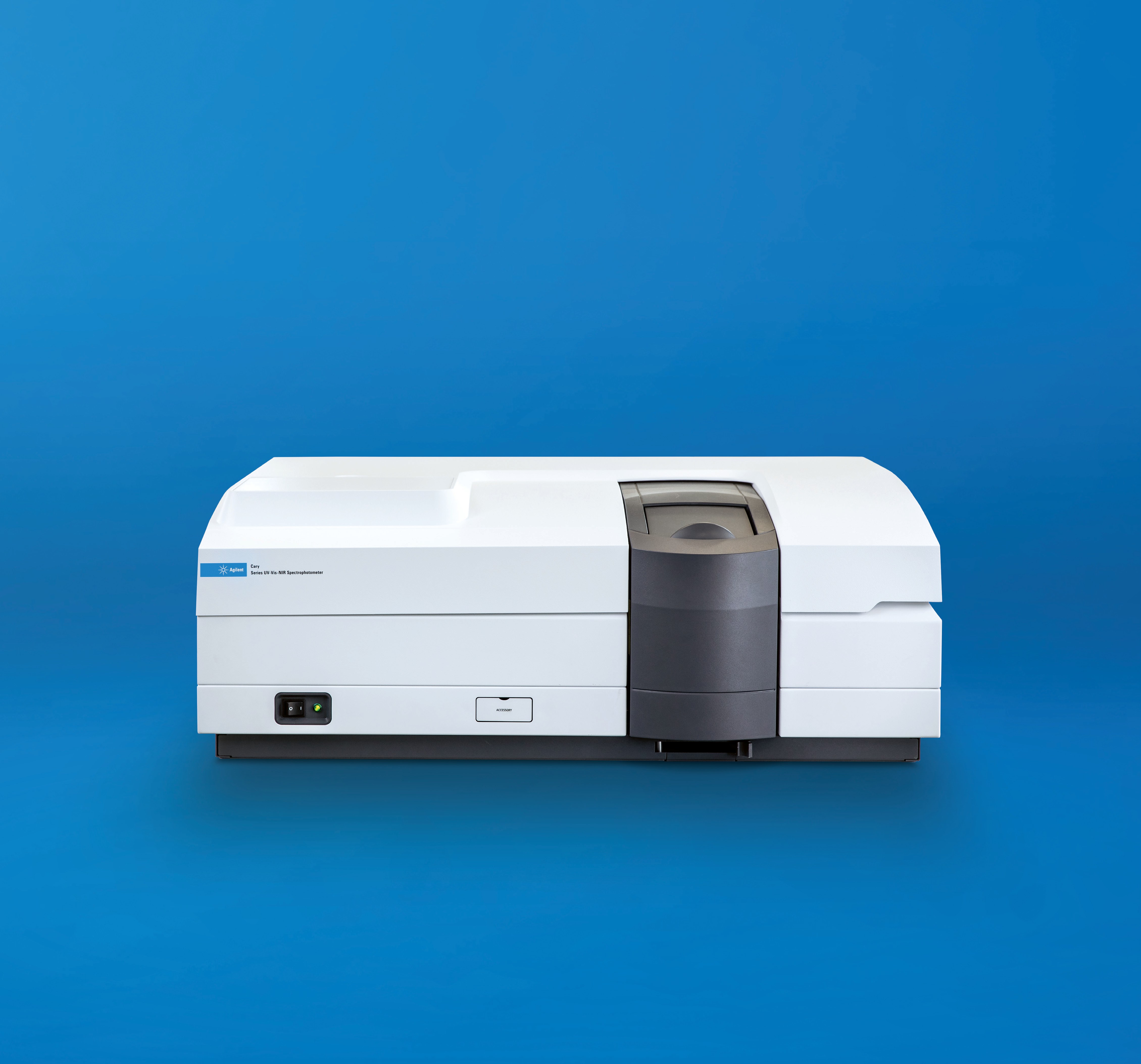
Agilent Technologies Cary 4000 UV-Vis
Agilent Technologies Cary 4000 UV-Vis — Molecular spectroscopy.
The Cary 4000 UV-Vis is a double-beam spectrophotometer with an out-of-plane double Littrow monochromator and silica-overcoated optics on a floating solid aluminium casting, covering 175–900 nm. It is the UV-Vis-only member of the Cary 4000/5000/6000i series, distinguished from the 5000 (to 3300 nm) and 6000i (to 1800 nm, InGaAs NIR) by its fixed slits and absence of NIR capability. It serves routine UV-Vis absorbance, transmittance and validation measurements in analytical laboratories.
Agilent Technologies Cary Series — Model Comparison & Selection
| Model | Wavelength range | Focused beam diameter, mm | Integrating sphere diameter, mm | Temperature range, °C |
|---|---|---|---|---|
| Cary 4000 UV-Vis Current | 175...900 | — | 150 | — |
| Cary 3500 | — | 1.5 | — | 5...110 |
| Cary 3500 Compact UV-Vis Spectrophotometer | — | 1.5 | — | 5...110 |
| Cary 3500 Flexible UV-Vis, Large Sample Compartment | — | 1.5 | — | — |
| Cary 5000 UV-Vis-NIR spectrophotometer | 175...900 | — | — | — |
| Cary 60 | 190...1,100 | — | — | — |
| Cary 6000i UV-Vis-NIR | 175...900 | — | 150 | — |
Full specifications
| Wavelength range | 175...900 nm |
| Integrating Sphere Diameter | 150 mm |
| Minimum Side Clearance | 50 mm |
| Warm-up Time | 2 hours |
| Optimized NIR region mfr | 1200...1800 nm |
| NIR detector mfr | InGaAs InGaAs |
| Optical design mfr | PbSmart PbSmart |
| Monochromator design mfr | out-of-plane double Littrow Littrow |
| Optics mfr | silica overcoated overcoated |
| Optical isolation mfr | floating solid aluminium casting casting |
| Lamp replacement mfr | pre-aligned, plug-and-go go |
| Slits mfr | fixed, in NIR as well as UV-Vis Vis |
| Minimum rear clearance mfr | 150 mm |
| Nitrogen operating pressure mfr | 83...172 kPa |
| Nitrogen supply tubing internal diameter mfr | 1 inch |
| Verifying Safe State mfr | 5 |
| Ultraviolet radiation mfr | 6 |
| Electrical hazards mfr | 6 |
| Other precautions mfr | 7 |
| Information symbols mfr | 8 |
| Color coding mfr | 9 |
| Starting the software mfr | 13 |
| Software Status Bulletin mfr | 14 |
| Setting up the instrument mfr | 15 |
| Turning on the system mfr | 16 |
| Instrument performance tests mfr | 17 |
| Sample holders mfr | 17 |
| Installing the base plate mfr | 25 |
| Installing other accessories mfr | 25 |
| Nitrogen purging mfr | 26 |
| Removing the sample compartment base mfr | 28 |
| Cleaning mfr | 31 |
| Source lamps mfr | 32 |
| Fuses mfr | 32 |
| Spare Parts mfr | 33 |
| Rear clearance mfr | 150 mm |
| NIR grating mfr | 600 lines/mm |
| internal diffuse reflectance accessory range mfr | 110 mm |
| external diffuse reflectance accessory range mfr | 150 mm |
| Sample compartment high voltage pin mfr | 125 VDC |
| GPIB communications mfr | 14 |
Description
Construction and series positioning
- The Cary 4000 uses an out-of-plane double Littrow monochromator with silica-overcoated optics mounted on a floating solid aluminium casting for optical isolation.
- Wavelength range is 175–900 nm; slits are fixed in both the UV-Vis and (where fitted) NIR regions.
- Within the series, the Cary 5000 extends to 3300 nm and the Cary 6000i to 1800 nm with an InGaAs NIR detector and PbSmart optical design; the Cary 4000 is the UV-Vis-only configuration, so NIR-region specifications (1200–1800 nm optimized NIR, InGaAs detector, PbSmart) do not apply to this model.
- The sample compartment floor is completely removable for large apparatus; removing it loses optical alignment with respect to the floor, requiring realignment before microcell analyses.
Operation and media
- The instrument is controlled by Cary WinUV software; the Validate application runs performance tests against a major subset of instrument parameters, and failed tests require an Agilent representative.
- Nitrogen purging is supported for the Cary 4000/5000/6000i/7000: operating pressure 83–172 kPa (12–25 psig), instrument flow 0–20 L/min and sample compartment flow 0–10 L/min, using clean flexible plastic (PVC or equivalent) tubing of 6 mm (1/4 in.) internal diameter; rubber tubing must never be used.
- Compressed nitrogen must be dry, oil-free and uncontaminated; oil or water from the compression process can deposit on optics and void the warranty.
Installation, connection and control
- The rear panel provides an IEEE 488 (GPIB) connection; a National Instruments USB-GPIB-HS+ converter is used to interface the computer, with Cary WinUV installed first.
- The sample compartment 15-pin D-range connector carries high-voltage pins rated −1000 VDC and +125 VDC on the Cary 4000/5000/7000; one connector carries high voltage for diffuse reflectance accessory (DRA) detectors and must only be used with Agilent Internal and External DRAs.
- The Cary 4000/5000/6000i/7000 has a Universal Power Supply that adapts to the supply voltage, but the actual mains voltage must still be verified.
- Cell holders and the solid sample holder (Cary 4000/5000/6000i/7000 only) are aligned using the Align application at zero order with a 2.5 mm hexagonal balldriver; the solid sample holder must be fitted to the LockDown base plate before installation.
Integration & Operating Notes
Allow at least 50 mm (2 in.) on the sides and 150 mm (6 in.) at the rear of the system for free air circulation. Insufficient clearance can cause overheating and impaired performance, so bench space must be planned before installation.
The 15-pin D-range connector in the sample compartment has high-voltage pins rated −1000 VDC and +125 VDC on the Cary 4000/5000/7000. Accessory compatibility and safety planning must account for these voltages, and one connector is reserved for Agilent Internal and External DRAs only.
Nitrogen purging must be held at 83–172 kPa (12–25 psig) with instrument flow 0–20 L/min and sample compartment flow 0–10 L/min. Use clean flexible plastic (PVC or equivalent) tubing of 6 mm (1/4 in.) internal diameter; never use rubber tubing, and never use compressed nitrogen from a supplier who uses oil or water in the compression process.
The computer interfaces through a National Instruments USB-GPIB-HS+ converter connected between instrument and computer USB port. The procedure requires Cary WinUV software to be installed first; the rear IEEE 488 (GPIB) connection is used with a shielded IEEE-488 cable.
Before changing the deuterium or visible lamps, switch off the instrument, remove the power supply cable and allow the lamps to cool. Never touch the glass surfaces of new lamps; handle a lamp by its base using a soft cloth, since touching the envelope reduces efficiency. Lamp replacement is pre-aligned and plug-and-go.
Two operator-accessible fuses are located at the rear; replace only with the type and rating indicated in the Site Preparation Guide or on the rear of the instrument. If a fuse repeatedly blows, it may indicate other problems and a service call may be required rather than repeated replacement.
The floor of the Cary 4000/5000/6000i/7000 sample compartment is completely removable for large apparatus, but once removed, optical alignment with respect to the floor is lost. Realign the optics before performing any microcell analyses.
Selection & Integration Q&A
Choose the Cary 4000 for UV-Vis work limited to 175–900 nm with fixed slits. The Cary 5000 extends to 3300 nm and the Cary 6000i to 1800 nm with an InGaAs NIR detector and PbSmart optics; select those only if NIR measurement is required.
Use the rear IEEE 488 (GPIB) port with a shielded IEEE-488 cable and a National Instruments USB-GPIB-HS+ converter, installing Cary WinUV first. The sample compartment 15-pin D-range connector carries −1000 VDC and +125 VDC; the DRA connector must only be used with Agilent Internal and External DRAs.
Allow 50 mm side and 150 mm rear clearance for air circulation, keep the sample compartment empty with its lid closed at power-on, and warm up for 2 hours for optimum performance. The Universal Power Supply adapts to mains voltage, but the actual supply voltage must still be verified.
Nitrogen purge tubing (6 mm ID PVC or equivalent, never rubber), a pressure regulator and flowmeter, the USB-GPIB-HS+ converter and shielded IEEE-488 cable, replacement lamps, and the two rear fuses are not part of the base instrument. Lamp changes require power isolation and cool-down.