
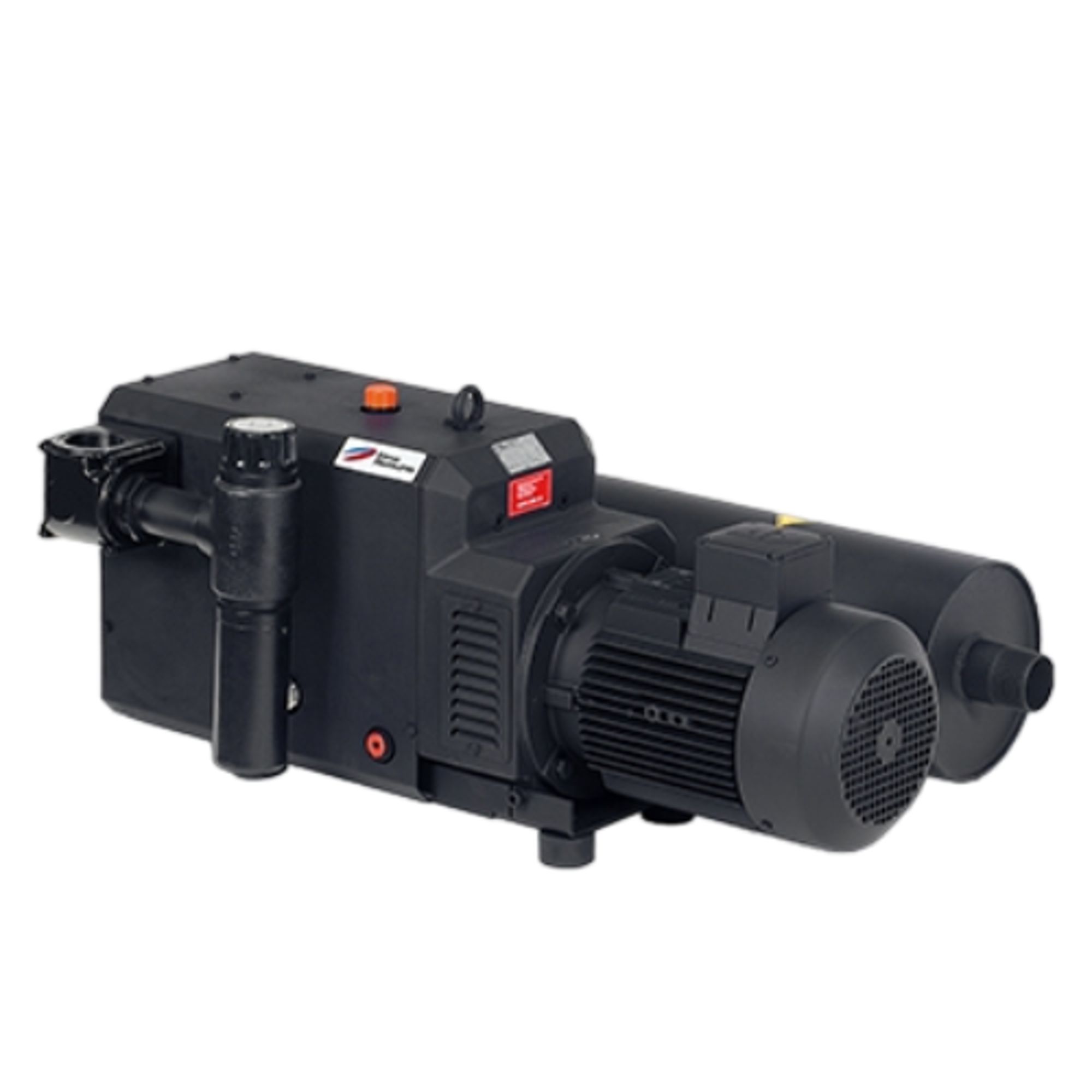
Elmo Rietschle C-VLR 1000
Elmo Rietschle C-VLR 1000 — Claw Vacuum Pumps with Motor power 18.5 kW, Pumping speed 950 m³/h, Ultimate pressure 200 mbar.
The C-VLR 1000 is a dry, contact-free claw vacuum pump with an 18.5 kW (50 Hz) / 22.0 kW (60 Hz) flanged three-phase motor, delivering 950 m³/h at 50 Hz and 1140 m³/h at 60 Hz with an ultimate vacuum of 200 mbar (abs). It is the largest single-stage model in the C-VLR series, distinguished by its high pumping speed and integrated air cooling, and is intended for continuous industrial vacuum generation in systems requiring oil-free operation.
Elmo Rietschle C-VLR Series — Model Comparison & Selection
Full specifications
| Lubrication type | dry |
| Motor power | 18.5 kW 50 Hz: 18.5 kW · 60 Hz: 22.0 kW |
| Operating principle | claw |
| Pumping speed | 950 m³/h |
| Ultimate pressure | 200 mbar |
| Rotational speed | 2945 rpm 50 Hz: 2945 rpm · 60 Hz: 3540 rpm |
| Suction capacity 60 Hz (alt var) mfr | 1140 m3/h |
| Speed 60 Hz (alt var) mfr | 3540 rpm |
| Suction capacity mfr | 950 m3/h (50 Hz) |
| Suction capacity mfr | 1140 m3/h (60 Hz) |
| Motor efficiency mfr | 92.4 % (50 Hz) |
| Motor efficiency mfr | 92.0 % (60 Hz) |
| Weight | 757 kg 50 Hz: 757 kg · 60 Hz: 755 kg |
| Power supply | 3~ AC |
| Motor rating 60 Hz (alt var) mfr | 22.0 kW |
| Rated voltage mfr | 400 / 690 V (50 Hz) |
| Rated voltage mfr | 380 / 660 V (60 Hz) |
| Current drawn mfr | 34.0 / 19.7 A (50 Hz) |
| Current drawn mfr | 41.8 / 24.0 A (60 Hz) |
| Oil capacity | 2.8 l |
| Noise level | 82 dB 50 Hz: 82 dB · 60 Hz: 83 dB |
| Protection rating | IP 55 |
| Cooling type | air |
| Average noise level 60 Hz (alt var) mfr | 83 dB |
Description
Construction and Series Positioning
The C-VLR 1000 uses two non-contacting claw rotors synchronised by an oil-lubricated gearbox, with bearings and gears isolated from the pumping chamber to maintain dry operation. The pump is supplied with a standard flanged three-phase motor (IP 55, insulation class F) and is available with either a plug connection or motor protection switch. Within the C-VLR series, the 1000 is the highest-capacity single-stage model, offering 950 m³/h at 50 Hz compared to 290 m³/h for the C-VLR 301 and lower capacities for the C-VLR 150 and C-VLR 60. It is therefore selected when the required suction capacity exceeds the range of smaller siblings, while the ultimate pressure of 200 mbar (abs) is slightly higher (less deep) than the 150 mbar of the C-VLR 301.
Performance and Operating Behaviour
The pump is designed for continuous operation at any inlet pressure between atmospheric and 200 mbar (abs). Suction capacity is 950 m³/h at 50 Hz and 1140 m³/h at 60 Hz, with corresponding motor ratings of 18.5 kW and 22.0 kW. The speed is 2945 rpm at 50 Hz and 3540 rpm at 60 Hz. Noise level is 82 dB at 50 Hz and 83 dB at 60 Hz. Weight is 757 kg at 50 Hz and 755 kg at 60 Hz. Performance data are based on PNEUROP standards with a tolerance of ±10%, and actual capacity depends on intake pressure per the data sheet. The dry claw principle allows oil-free conveyance of air, nitrogen, inert gases, and, for the XD variant, non-explosive damp gases. The pump is not suitable for liquids or explosive atmospheres.
Installation, Connections and Control
The pump must be installed horizontally with a maximum inclination of 5° in all directions. Cooling air inlets and outlets require at least 30 cm clearance from walls, and 40 cm must be kept free in front of the mesh filter for maintenance. The vacuum connection is flange DN 100 PN 6 (or PN 10 option X2), and the exhaust is flange DN 100 PN 10. Pipes must be screwed in by hand only, and flexible connections are recommended to avoid excessive forces. A non-return valve is required if suction lines longer than 3 m are used. The exhaust line must not be restricted; maximum permissible back pressure is 30 mbar (50 mbar for the HV+ central unit). Electrical connection requires a motor protection switch with overload-dependent delayed trip, and rotation direction must be verified by brief start (max. 2 s) – the motor fan must rotate clockwise when viewed from the fan. The pump is air-cooled and requires no additional cooling medium.
Integration & Operating Notes
The pump must be set up on a level, even floor with a maximum inclination of 5° in all directions to ensure proper oil distribution and lubrication. Exceeding this limit can cause inadequate lubrication, increased wear, and potential damage to the gearbox and bearings. Secure the unit against tipping and verify the foundation can support the operating weight of 757 kg (50 Hz) or 755 kg (60 Hz).
The exhaust air outlet must remain unrestricted; do not install blocking devices such as valves or dampers in the exhaust line. The maximum permissible pressure difference on the exhaust side is 30 mbar. Higher back pressure reduces pumping capacity and can cause overheating, ultimately leading to motor overload or mechanical damage. Size exhaust piping and silencers for low pressure drop and inspect regularly for blockages.
After electrical connection, briefly start the motor (max. 2 seconds) and confirm the motor fan rotates clockwise when viewed from the fan. Incorrect rotation direction will damage the pump because the claw rotors are not designed to run backwards. Use a phase sequence indicator to check for a clockwise rotating field. This check is mandatory before connecting the suction line to the process.
The gearbox and bearing lubrication oil must be changed every 8,000 operating hours under clean operating conditions. Use only oil meeting ISO VG 150 per DIN 51519, such as GEARLUBE 150 or equivalent. Drain the oil at operating temperature and in a well-ventilated area. The correct fill quantity is 2.8 litres, filled to the middle of the sight glass. Overfilling or underfilling can lead to overheating or inadequate lubrication. Also clean the mesh filter regularly and check the oil level monthly.
The permitted ambient and suction temperature range is 5 to 40 °C. Operating outside this range may cause overheating, reduced performance, and void the warranty. For high ambient temperatures or frequent switching (approx. 10 times per hour), the motor winding and bearing temperature limits may be exceeded; consult the manufacturer for such duty cycles. Ensure adequate ventilation to maintain the ambient temperature within limits.
If the suction line has the same cross-section as the pump connection and exceeds 3 m in length, a non-return valve must be installed in the suction line. This prevents reverse rotation of the pump after shutdown due to the inertia of the air column in the long pipe, which can damage the claw mechanism. The integrated non-return valve (if present) must not be removed or modified; check it regularly for proper function.
Selection & Integration Q&A
Choose the C-VLR 1000 when your required suction capacity exceeds 290 m³/h (the C-VLR 301's maximum) and you need up to 950 m³/h at 50 Hz. The C-VLR 1000 also offers a slightly higher ultimate pressure of 200 mbar (abs) versus 150 mbar for the C-VLR 301, so if deeper vacuum is critical, the 301 may be preferred. The 1000 is the highest-capacity single-stage model in the series.
The suction connection is flange DN 100 PN 6 (or PN 10 option X2), and the exhaust is flange DN 100 PN 10. Use flexible connections to avoid transmitting forces to the pump, and screw pipes in by hand only. If the suction line is longer than 3 m, install a non-return valve. The exhaust line must not be restricted; maximum back pressure is 30 mbar. Ensure piping is sized to keep pressure drop low.
The permitted ambient and suction temperature range is 5 to 40 °C. Continuous operation is allowed at any inlet pressure between atmospheric and 200 mbar (abs). However, frequent switching (about 10 times per hour) or high ambient/inlet temperatures may exceed motor winding and bearing temperature limits; consult the manufacturer for such conditions. Above 1000 m altitude, motor derating is required.
The base pump does not include suction filter (ZVF 100), motor starter (ZMS), exhaust silencer (ZRZ 100), or non-return leaf. These must be ordered separately. Maintenance parts such as oil (ISO VG 150, 2.8 L), mesh filter, and coupling element are wearing parts and should be stocked. Oil changes are required every 8,000 hours; the coupling is maintenance-free but the elastomer element should be inspected.