
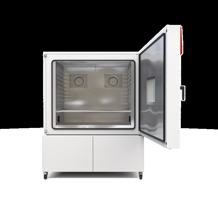
BINDER MKF 1020 CO₂
BINDER MKF 1020 CO₂ — Climate chambers with Temperature -48…180 °C.
The MKF 1020 CO₂ is a 991 L alternating climate chamber with a working range of -48…180 °C and 10…98 % RH, extending the MKF series downward by 8 K versus the standard MKF 1020. Its 11.5 kW 400 V 3 N/PE 50 Hz supply and 1400 W heat compensation support rapid temperature cycling (6.2 K/min heating, 4.8 K/min cooling) for large-volume test loads.
BINDER MKF Series — Model Comparison & Selection
| Model | Temperature, °C | Height, cm | Interior volume, L | Load per rack, kg | Max heat compensation, W | Nominal power, kW |
|---|---|---|---|---|---|---|
| MKF 1020 CO₂ Current | -48–180 | 200.5 | 991 | 40 | 1400 | 11.5 |
| MKF 1020 | -40–180 | 200.5 | 991 | 40 | 1500 | 12.5 |
| MKF 115 | -40–180 | 172.5 | 115 | 30 | 400 | 4.8 |
| MKF 240 | -40–180 | 171.5 | 228 | 30 | 400 | 6.8 |
| MKF 240 CO₂ | -50...180 | 171.3 | 228 | 30 | 900 | 6.8 |
| MKF 400 | -40–180 | 171 | 417 | 30 | 800 | 8 |
| MKF 400 CO₂ | -50...180 | 172.7 | 417 | 30 | 1600 | 7.9 |
| MKF 56 | -40–180 | 144.5 | 60 | 15 | 250 | 2.8 |
| MKF 720 | -40–180 | 200.5 | 734 | 40 | 1000 | 11 |
| MKF 720 CO₂ | -48–180 | 200.5 | 734 | 40 | 1100 | 11 |
Full specifications
| Temperature | -48...180 °C |
| Interior volume | 991 L (MKF1020O2-400V, 50 Hz) |
| Load per rack | 40 kg (MKF1020O2-400V, 50 Hz) |
| Maximum heat compensation | 1400 W |
| Nominal power | 11.5 kW (MKF1020O2-400V, 50 Hz) |
| Article Number mfr | 9020 |
| Depth | 1480 mm (MKF1020O2-400V, 50 Hz) |
| Height | 2005 mm (MKF1020O2-400V, 50 Hz) |
| Width | 1580 mm (MKF1020O2-400V, 50 Hz) |
| Power frequency | 50 Hz (MKF1020O2-400V) |
| Rated voltage | 400 V |
| Unit fuse | 32.0 A (MKF1020O2-400V, 50 Hz) |
| Humidity range | 10...98 % RH |
| Cooling down time from 180°C to -40°C mfr | 70 min |
| Humidity fluctuation with humidity dependent on set value mfr | 2 % r.F. |
| Average heating-up rate according to IEC 60068-3-5 between -40°C and 180°C mfr | 6.2 K/min |
Description
Construction and series positioning
- The MKF 1020 CO₂ is the CO₂-refrigerant variant of the MKF 1020, sharing the 991 L interior volume and 1580 × 1480 × 2005 mm net envelope but extending the low-temperature limit to -48 °C (vs. -40 °C for the standard MKF 1020 and MKF 240/115).
- Unlike the smaller MKF 240 CO₂ (-50…180 °C), this model prioritizes volume over ultimate cold limit, making it the choice for large test batches requiring moderate sub-zero capability.
- Refrigeration uses R 744 (CO₂) with a maximum operating pressure of 120 bar; repairs to the circuit are restricted to BINDER.
Behavior under load and in different media
- Temperature uniformity is 0.1…1.0 K and fluctuation 0.1…0.2 K depending on set value; with humidity active, the range narrows to 10…95 °C and humidity fluctuation is 2 % r.F.
- Average heating rate from -40 °C to 180 °C is 6.2 K/min; cooling from 180 °C to -40 °C averages 4.8 K/min, with a total cooling-down time of 70 min.
- Maximum heat compensation is 1400 W, allowing the chamber to hold setpoint against heat dissipated by powered test specimens; load per rack is limited to 40 kg.
Installation, connection and control
- The chamber requires a 400 V 3 N/PE 50 Hz supply with 32.0 A unit fuse and a type B residual current circuit breaker; voltage tolerance is ±10 % at the indicated frequency.
- Water interfaces include freshwater supply (automatic via pipe or manual via internal can) and wastewater connection; a condensate recycling lever and hose burst/reflux safety kit are options.
- The MB2 controller provides fixed-value, time-program and week-program modes, a chart-recorder display, zero-voltage switching outputs, and optional RS485, analog outputs, and Pt 100 object sensor.
Integration & Operating Notes
The chamber label and manual require operation only with residual current circuit breakers type B; standard type A or AC devices may not detect DC fault currents from the CO₂ refrigeration drive and are not permitted.
Because the refrigerant is CO₂ (R 744) at up to 120 bar, the installation room volume must be calculated according to EN 378-1:2016+A1:2020; do not install in unventilated recesses and observe minimum distances from Chapter 3.4.
The humidity sensor has tabulated maximum workplace concentrations for ammonia, acetone, ethanol, formaldehyde, ozone and others; permanent load above these limits will degrade or destroy the sensor, so test loads emitting such substances must be evaluated before humid operation.
After 8760 operating hours or two years the controller displays a service message; once acknowledged it reappears every two weeks until reset by BINDER Service, so plan the service interval to avoid recurring production interruptions.
The door gasket must be replaced only when cold; attempting replacement while warm can damage the gasket and compromise the seal, so allow the chamber to cool to ambient before service.
Condensers should be cleaned every 1 to 2 years by a qualified technician; with increased dust, check the fan grid behind the left maintenance access flap weekly and suction-clean if visibly dirty after disconnecting the chamber.
Selection & Integration Q&A
Pick the MKF 1020 CO₂ when you need 991 L capacity and a -48 °C lower limit; the standard MKF 1020 stops at -40 °C. Choose the MKF 240 CO₂ only if -50 °C is required and 240 L suffices.
A 400 V 3 N/PE 50 Hz supply with 32.0 A fuse and a type B RCD; voltage tolerance is ±10 %. Nominal power is 11.5 kW, so size the feeder and upstream protection for the full load.
Freshwater (pipe or internal can) and wastewater connections are required. The condensate recycling lever, hose burst/reflux safety kit, and connection kit for freshwater pipe are options not in base delivery.
Annual maintenance and steam humidifier service at least yearly; condenser cleaning every 1–2 years; electrical safety test per EN 50678/50699 before first start and after repair; service message at 8760 h or two years until BINDER reset.