
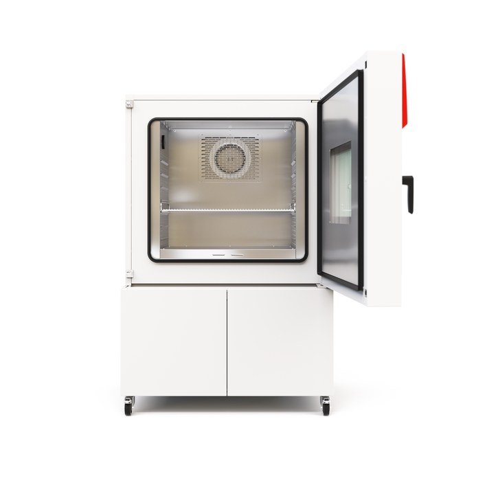
BINDER MKF 240 CO₂
BINDER MKF 240 CO₂ — Climate chambers.
The MKF 240 CO₂ is a 228 L alternating climate chamber with a working range of -50 to 180 °C and 10 to 98 % RH, distinguished within the MKF series by its extended low-temperature limit and CO₂ refrigerant circuit. It is intended for programmed temperature/humidity cycling of test specimens in a laboratory, with a 900 W heat compensation capacity for active loads.
BINDER MKF Series — Model Comparison & Selection
| Model | Temperature, °C | Height, cm | Interior volume, L | Load per rack, kg | Max heat compensation, W | Nominal power, kW |
|---|---|---|---|---|---|---|
| MKF 240 CO₂ Current | -50...180 | 171.3 | 228 | 30 | 900 | 6.8 |
| MKF 1020 | -40–180 | 200.5 | 991 | 40 | 1500 | 12.5 |
| MKF 1020 CO₂ | -48–180 | 200.5 | 991 | 40 | 1400 | 11.5 |
| MKF 115 | -40–180 | 172.5 | 115 | 30 | 400 | 4.8 |
| MKF 240 | -40–180 | 171.5 | 228 | 30 | 400 | 6.8 |
| MKF 400 | -40–180 | 171 | 417 | 30 | 800 | 8 |
| MKF 400 CO₂ | -50...180 | 172.7 | 417 | 30 | 1600 | 7.9 |
| MKF 56 | -40–180 | 144.5 | 60 | 15 | 250 | 2.8 |
| MKF 720 | -40–180 | 200.5 | 734 | 40 | 1000 | 11 |
| MKF 720 CO₂ | -48–180 | 200.5 | 734 | 40 | 1100 | 11 |
Full specifications
| Temperature | -50...180 |
| Interior volume | 228 L (MKF240CO2-400V, 50 Hz) |
| Load per rack | 30 kg (MKF240CO2-400V, 50 Hz) |
| Maximum heat compensation | 900 W |
| Nominal power | 6.8 kW (MKF240CO2-400V, 50 Hz) |
| Article Number mfr | 9020 |
| Depth | 925 mm (MKF240CO2-400V, 50 Hz) |
| Height | 1713 mm (MKF240CO2-400V, 50 Hz) |
| Width | 1115 mm (MKF240CO2-400V, 50 Hz) |
| Power frequency | 50 Hz (MKF240CO2-400V) |
| Rated voltage | 400 V |
| Unit fuse | 16.0 A (MKF240CO2-400V, 50 Hz) |
| Humidity range | 10...98 % RH |
| Cooling down time from 180°C to -40°C mfr | 60 min |
| Humidity fluctuation with humidity dependent on set value mfr | 2 % r.F. |
| Average heating-up rate according to IEC 60068-3-5 between -40°C and 180°C mfr | 5.5 K/min |
Description
Construction and series positioning
- The MKF 240 CO₂ is the 240-size cabinet of the MKF (E6) series, with 228 L interior volume and net dimensions 1,115 mm wide × 925 mm deep × 1,713 mm high.
- Within the series it is the CO₂-refrigerant modification of the MKF 240: the standard MKF 240 and MKF 115 are rated -40…180 °C, while this model reaches -50 °C at the low end. The larger MKF 1020 and MKF 1020 CO₂ are separate cabinet sizes, not options of this unit.
- The refrigeration circuit uses R 744 (CO₂) at a maximum operating pressure of 120 bar; repairs to this circuit are currently only performed at BINDER.
Working behavior
- Temperature range is -50…180 °C; with humidity active the range is restricted to 10…95 °C and 10…98 % RH.
- Factory figures: temperature uniformity 0.1…1.2 K and fluctuation 0.1…0.4 K depending on set value; with humidity, fluctuation 0.1…1 K and humidity fluctuation 2 % r.F.
- Average heating rate per IEC 60068-3-5 is 5.5 K/min between -40 °C and 180 °C; cooling from 180 °C to -40 °C takes 60 min.
- Maximum heat compensation is 900 W, so active specimens up to that load can be held at set point; each rack carries up to 30 kg.
Installation, control and operation
- Electrical supply is 400 V 3 N/PE 50 Hz, nominal power 6.8 kW, unit fuse 16.0 A; supply tolerance is ±10 % at the indicated frequency, and a type B residual current circuit breaker is required.
- Humidity control needs a freshwater supply (automatic via water pipe or manual via internal freshwater can) and a wastewater connection; a condensate recycling lever and a hose burst/reflux safety kit are available as options.
- The MB2 chamber controller provides fixed-value, timer, time-program and week-program modes, a chart-recorder display, alarm/notification handling, user authorization levels, and serial/Ethernet/USB interfaces; RS485 and analog temperature/humidity outputs are options.
- Temperature safety is provided by an over-temperature protective device (class 1) and a safety controller (class 2.0 per DIN 12880), with an optional over/under-temperature class 2 device.
- The chamber is IP 20 (EN 60529) and must not be installed in unventilated recesses; room volume must be verified per EN 378-1:2016+A1:2020 and minimum clearances observed.
Integration & Operating Notes
The chamber is labeled for operation only with residual current circuit breakers type B, and the nominal voltage tolerance is ±10 % at the indicated power frequency. Size the feeder for 6.8 kW / 16 A at 400 V 3 N/PE 50 Hz and verify the actual type plate before connection.
With humidity control active the chamber is limited to 10…95 °C and 10…98 % RH, so programs that combine low-temperature phases below 10 °C with humidification are not permissible. Plan test profiles so that humidity sections stay inside this window.
The humidity sensor has tabulated maximum workplace concentrations for substances such as ammonia, acetone, chlorine, acetic acid, ethanol, formaldehyde, ozone, hydrochloric acid, hydrogen sulphide, sulphur dioxide and xylene. Permanent exposure above these limits damages the sensor, so specimens outgassing such substances must be evaluated before testing.
Required room volume must be calculated per EN 378-1:2016+A1:2020 because of the CO₂ refrigerant charge, and installation in unventilated recesses is prohibited. Observe the minimum distances of chapter 3.4 so that heat from the refrigeration circuit can disperse.
After 8760 operating hours or two years the controller displays a service message; after confirmation it reappears every two weeks until reset by BINDER Service. Plan the annual maintenance and the BINDER Service reset together so the recurring message does not interrupt long test programs.
Condensers should be cleaned every 1 to 2 years by a qualified technician, and the steam humidifier requires maintenance at least once a year, with frequency depending on water quality and steam output. In dusty ambient air the condenser fan grid behind the left maintenance access flap must be checked weekly and cleaned by suction after disconnecting the chamber.
The door gasket must be replaced only when the chamber is cold; replacing it warm can damage the gasket. Allow the chamber to cool to ambient before any gasket service, and include this in the maintenance procedure.
An annual repeat electrical inspection is required, plus a test prior to initial startup and prior to resuming operation after maintenance or repair, recommended per EN 50678/VDE 0701 and EN 50699/VDE 0702. Build this test into the commissioning and service workflow.
Selection & Integration Q&A
Pick the MKF 240 CO₂ when you need the -50 °C low limit in a 228 L cabinet; the standard MKF 240 stops at -40 °C. Choose the MKF 1020 CO₂ only if the larger cabinet volume is required, since it is a different size class, not an option of this model.
Humidity control requires a freshwater supply, either automatic via a water pipe with the connection kit or manual via the internal freshwater can, plus a wastewater connection. A condensate recycling lever and a hose burst/reflux safety kit are available as options and should be specified at order time.
No. Installation in unventilated recesses is prohibited, and the required room volume must be calculated per EN 378-1:2016+A1:2020 because of the CO₂ refrigerant charge. Observe the minimum distances of chapter 3.4 so refrigeration heat can disperse.
The base unit does not include the RS485 interface, analog temperature/humidity outputs, flexible Pt 100 object sensor, condensate recycling lever, hose burst/reflux safety kit, APT-COM 4 software or BINDER Pure Aqua Service. Plan annual maintenance, condenser cleaning every 1–2 years, yearly steam humidifier service and the 8760 h/two-year BINDER Service reset.