
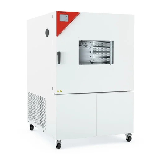
BINDER MKF 400
BINDER MKF 400 — Climate chambers with Temperature -40…180 °C.
The BINDER MKF 400 is a 417 L alternating climate chamber with a working range of -40 to 180 °C and 10–98 % RH, designed for rapid temperature cycling at up to 5 K/min. It is the mid-size 400 V model in the MKF series, positioned between the MKF 240 and MKF 720, and is intended for climatic stress testing and humidity-controlled conditioning in a laboratory or industrial test environment.
BINDER MKF Series — Model Comparison & Selection
| Model | Temperature, °C | Height, cm | Interior volume, L | Load per rack, kg | Max heat compensation, W | Nominal power, kW |
|---|---|---|---|---|---|---|
| MKF 400 Current | -40–180 | 171 | 417 | 30 | 800 | 8 |
| MKF 1020 | -40–180 | 200.5 | 991 | 40 | 1500 | 12.5 |
| MKF 1020 CO₂ | -48–180 | 200.5 | 991 | 40 | 1400 | 11.5 |
| MKF 115 | -40–180 | 172.5 | 115 | 30 | 400 | 4.8 |
| MKF 240 | -40–180 | 171.5 | 228 | 30 | 400 | 6.8 |
| MKF 240 CO₂ | -50...180 | 171.3 | 228 | 30 | 900 | 6.8 |
| MKF 400 CO₂ | -50...180 | 172.7 | 417 | 30 | 1600 | 7.9 |
| MKF 56 | -40–180 | 144.5 | 60 | 15 | 250 | 2.8 |
| MKF 720 | -40–180 | 200.5 | 734 | 40 | 1000 | 11 |
| MKF 720 CO₂ | -48–180 | 200.5 | 734 | 40 | 1100 | 11 |
Full specifications
| Temperature | -40...180 °C |
| Interior volume | 417 L (MKF400-400V, 50 Hz) |
| Load per rack | 30 kg (MKF400-400V, 50 Hz) |
| Maximum heat compensation | 800 W |
| Nominal power | 8 kW (MKF400-400V, 50 Hz) |
| Article Number mfr | 9020 |
| Depth | 1400 mm (MKF400-400V, 50 Hz) |
| Height | 1710 mm (MKF400-400V, 50 Hz) |
| Width | 1115 mm (MKF400-400V, 50 Hz) |
| Power frequency | 50 Hz (MKF400-400V) |
| Rated voltage | 400 V |
| Unit fuse | 16.0 A (MKF400-400V, 50 Hz) |
| Humidity range | 10...98 % RH |
| Cooling down time from 180°C to -40°C mfr | 115 min |
| Humidity fluctuation with humidity dependent on set value mfr | 2.5 % r.F. |
| Average heating-up rate according to IEC 60068-3-5 between -40°C and 180°C mfr | 5.0 K/min |
Description
Construction and positioning
- The MKF 400 uses a 400 V, 3-phase/N/PE, 50 Hz electrical supply (nominal power 8 kW, unit fuse 16 A) and is available as the standard MKF400-400V (Art. No. 9020-0408) or the MKF400-480V-C variant with an integrated voltage and frequency changer for 480 V/60 Hz networks.
- With 417 L interior volume and net dimensions of 1,115 mm (W) × 1,710 mm (H) × 1,400 mm (D), it sits between the MKF 240 and MKF 720 in the series; unlike the smaller MKF 56, it uses a rear power switch in addition to the main power switch and supports the water circle lever for condensate recycling.
- The chamber is equipped with the MB2 controller, which provides fixed-value, time-program, and week-program operating modes, as well as alarm and notification functions.
Behavior under load and in different media
- Temperature uniformity is 0.1–1.2 K and fluctuation 0.1–0.5 K, depending on set value; with humidity active, the temperature range is restricted to 10–95 °C, with temperature fluctuation 0.1–1.3 K and humidity fluctuation 2.5 % RH.
- Average heating and cooling rates are 5.0 K/min (per IEC 60068-3-5) between -40 °C and 180 °C; a full cooling down from 180 °C to -40 °C takes 115 minutes.
- Maximum heat compensation is 800 W, allowing the chamber to maintain set points under heat dissipation from test specimens; the load per rack is limited to 30 kg.
Installation, connection, and control
- Water connections are required for humidity control: freshwater supply (automatic via water pipe or manual via internal freshwater can from size 115 on) and wastewater drain; the water circle lever for condensate recycling is available as an option.
- The rear power switch must be turned on in addition to the main power switch for operation; electrical connection must be made by qualified personnel, and the unit fuse rating of 16 A must be respected.
- The MB2 controller supports set-point entry in fixed-value mode, time and week programs with ramp/step functions, and a chart recorder display; user management with password protection is available.
- Temperature safety devices include an over-temperature protective device (class 1) and a safety controller (class 2) with adjustable modes; an optional over/under temperature safety device class 2 is available.
Integration & Operating Notes
The MKF 400 draws 8 kW nominal power from a 3 N/PE 400 V 50 Hz supply and must be protected by a 16 A fuse. Verify that the site provides this configuration; for 480 V/60 Hz networks, the -C variant with voltage and frequency changer is required. Incorrect voltage or fusing can damage the chamber and void warranty.
When humidity is active, the temperature range is restricted to 10–95 °C; outside this range, humidity control must be switched off. This affects test profiles that combine low or high temperatures with humidity: ensure that the set points remain within the humidity-compatible range or disable humidity control accordingly.
Regular maintenance at least once a year is required, including a leak test per Regulation (EU) 517/2014. The steam humidifier must be maintained at least annually, with intervals depending on water quality and steam production. Condensers should be cleaned every 1–2 years by a qualified technician. Document all service in the log book.
After 8760 operating hours or two years, a service message appears on the controller. After confirmation, it reappears every two weeks until reset by BINDER Service. Plan for a BINDER Service intervention to reset the message and perform any required maintenance at that time.
For sizes 115 and above, including the MKF 400, a rear power switch is provided in addition to the main power switch. Both must be turned on during commissioning and troubleshooting. Ensure accessible clearance at the rear for operating this switch and for maintenance access.
The humidity sensor has resistance limits for certain gases: ammonia (NH3) maximum workplace threshold 20 ppm / 14 mg/m³ and permanent load 5500 ppm / 4000 mg/m³; ozone (O3) 0.1 ppm / 0.2 mg/m³ and 0.5 ppm / 1 mg/m³. Verify that process atmospheres do not exceed these concentrations to avoid sensor damage.
Selection & Integration Q&A
Choose the MKF 400 when you need 417 L interior volume and 30 kg per rack load, with the same -40…180 °C range and 5 K/min ramp rates as the series. The MKF 240 offers smaller capacity, while the MKF 720 provides larger volume; select based on test specimen size and throughput requirements.
The standard MKF400-400V requires a 400 V, 3-phase/N/PE, 50 Hz supply with 16 A fusing and 8 kW nominal power. For 480 V/60 Hz networks, specify the MKF400-480V-C variant, which includes a voltage and frequency changer.
Annual maintenance including leak test per EU 517/2014; steam humidifier maintenance at least yearly (more often with poor water quality); condenser cleaning every 1–2 years; weekly fan grid check in dusty environments; service message reset by BINDER Service after 8760 h or two years.
The base MKF 400 does not include the water cooling option, water circle lever for condensate recycling, compressed air dryer, or external freshwater/wastewater cans (the latter only for MKF 56). Also, the disinfectant spray (Art. No. 1002-0022) and any interface cables for RS485 or analog outputs must be ordered separately.