
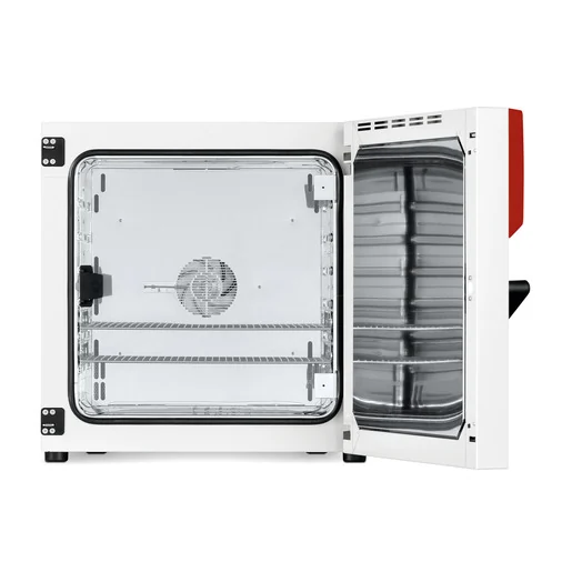
BINDER BF 115
BINDER BF 115 — Incubators with Temperature 8…100 °C.
The BINDER BF 115 is a forced-convection incubator with a 114 L interior, adjustable fan speed in 10% steps, and a working range of +8 to 100 °C. Within the BF series it is the mid-size 115 variant, offering tighter uniformity (0.3 K) and fluctuation (0.1 K) than larger siblings. It is intended for incubation of cultures at 37 °C and precise tempering of harmless materials in laboratory workflows.
Direct drop-in replacements
BINDER BF Series — Model Comparison & Selection
Full specifications
| Temperature | 8...100 °C |
| Heating-up time to 100 °C | 65 min |
| Interior volume | 114 L (BF115-230V / BF115UL-120V) |
| Load per rack | 30 kg (BF115-230V / BF115UL-120V) |
| Nominal power | 0.4 kW |
| Permitted load | 150 kg (BF115-230V / BF115UL-120V) |
| Temperature fluctuation | 0.1 K |
| Temperature uniformity | 0.3 K |
| Back wall clearance | 160 mm (BF115-230V / BF115UL-120V) |
| Side wall clearance | 100 mm (BF115-230V / BF115UL-120V) |
| Article Number mfr | 9010 |
| Recovery time after door was opened for 30 s at 37°C mfr | 3 min |
| Depth | 605 mm (BF115-230V / BF115UL-120V) |
| Height | 725 mm (BF115-230V / BF115UL-120V) |
| Width | 710 mm (BF115-230V / BF115UL-120V) |
| Power frequency | 50 Hz |
| Rated voltage | 230 V |
| Unit fuse | 6.3 A |
| Phase (Nominal voltage) mfr | 1 |
Description
Construction and series positioning
The BF 115 (Art. No. 9010-0315, designation 115-230) is a 230 V 1~ 50 Hz forced-convection incubator with a 114 L net interior (710 mm W × 725 mm H × 605 mm D). Unlike the natural-convection BD series, the BF series uses a fan whose speed is adjustable in 10% increments, enabling tuning of airflow versus temperature uniformity. Within the BF series, the 115 size sits between the 56 and 260 models; its +8 °C lower temperature limit is slightly higher than the +7 °C of the BF 56/260 and lower than the +10 °C of the BF 720, reflecting its specific cooling/control configuration. The chamber is equipped with a glass door and racks rated at 30 kg each, with a total permitted load of 150 kg.
Behavior under load and in operation
Temperature control is specified with a fluctuation of 0.1 K and a uniformity of 0.3 K, supported by forced convection. Heating from ambient to 100 °C takes 65 minutes. After a 30 s door opening at 37 °C, recovery takes 3 minutes. The controller displays temperature with 0.1 °C resolution. The safety controller set-point range is 10 °C to 100 °C (accuracy 0.1 °C) and should be set 2–5 °C above the working set-point. The overtemperature protective device class 1 trips at 120 °C. Loading must respect at least 10% wall clearance and must not exceed half of the usable volume to maintain airflow and homogeneity.
Installation, connection and control
Installation requires indoor, non-flammable surface with 160 mm rear and 100 mm side wall clearance. Ambient conditions: +18 to +40 °C, max 70% r.h. non-condensing, max 2000 m altitude. Electrical supply: 230 V 1~ 50 Hz, nominal power 0.4 kW, external chamber fuse 6.3 A time-lag (T) 5×20 mm / 250 V; supply tolerance ±10%. The chamber uses an IEC connector plug with shockproof plug. Control is via the R4 controller with menu-driven set-point entry for temperature and fan speed; timer functions include Delayed Off and Temperature-dependent Delayed Off/Delayed On. Ethernet is optional (standard only on FED). USB interface supports data recording. The chamber is IP 20 and pollution degree 2 / over-voltage category II per IEC 61010-1.
Integration & Operating Notes
Insufficient wall clearance restricts airflow around the chamber, causing overheating of components and impaired temperature uniformity. The manual specifies these minimum distances for indoor installation on a non-flammable surface; do not install in unventilated recesses.
The chamber is rated for 230 V 1~ 50 Hz with a nominal power of 0.4 kW and an external 6.3 A time-lag fuse. Voltage fluctuations beyond ±10% can cause malfunction or damage; verify supply quality against the type plate before connection.
The safety controller acts as an absolute maximum temperature limit. After any change to the temperature set-point, re-adjust the safety controller set-point to 2–5 °C above it to prevent nuisance trips or inadequate protection. The permissible range is 10–100 °C with 0.1 °C accuracy.
Samples must remain within the usable volume with at least 10% of interior dimensions as wall clearance. Overloading or placing samples too close to walls prevents sufficient airflow and homogeneous temperature distribution, compromising uniformity and recovery performance.
The chamber must be maintained at least once a year by licensed electricians or BINDER-authorized experts. An annual repeat electrical inspection per EN 50678/VDE 0701 and EN 50699/VDE 0702 is recommended. Warranty is void if maintenance is performed by non-authorized personnel.
Replacing the door gasket while the chamber is hot may damage the gasket material and impair sealing. Allow the chamber to cool to ambient before replacement. Racks can be removed and autoclaved; use neutral cleaning agent art. no. 1002-0016 and disinfectant spray art. no. 1002-0022.
The chamber has no explosion protection. Charging material must not be explosive, flammable, or form an explosive mixture with air, and operating temperature must be below its flash point. Corrosive ingredients such as acids and halides can damage stainless steel, aluminum, and copper components and are excluded from liability.
Selection & Integration Q&A
Choose BF 115 for 114 L capacity with +8 °C lower limit and 0.4 kW power. BF 56 offers smaller volume and +7 °C; BF 260 gives larger capacity but higher power (0.9 kW). Select based on sample volume and required temperature range.
Annual maintenance by authorized personnel and annual electrical safety test per EN 50678/EN 50699 are required. Recommended cleaning agents: neutral cleaner art. 1002-0016 and disinfectant spray art. 1002-0022. Ethernet is optional; USB data recording is available. Racks are included but additional racks may be ordered.