BINDER MK 115
BINDER MK 115 — Climate chambers with Temperature -40…180 °C.
The BINDER MK 115 is a 115-litre dynamic climate chamber with a working range of -40 to 180 °C, built for rapid temperature changes at up to 5.3 K/min heating. It is the mid-size 400 V three-phase model in the MK series, positioned between the 56-litre and 240-litre siblings. Its primary purpose is controlled temperature cycling of test specimens in laboratory and industrial qualification processes.
BINDER MK Series — Model Comparison & Selection
| Model | Temperature, °C | Depth, cm | Height, cm | Interior height, mm | Interior volume, L | Interior width, mm |
|---|---|---|---|---|---|---|
| MK 115 Current | -40–180 | 86.5 | 172.5 | 480 | 115 | 600 |
| MK 1020 | -40–180 | 148 | 200.5 | 1020 | 991 | 1200 |
| MK 1020 CO₂ | -48–180 | 148 | 200.5 | 1020 | 991 | 1200 |
| MK 240 | -40–180 | 92.5 | 171 | 700 | 228 | 735 |
| MK 240 CO₂ | -50...180 | 92.5 | 171 | 700 | 228 | 735 |
| MK 400 | -40–180 | 140 | 171 | 700 | 417 | 735 |
| MK 400 CO₂ | -50...180 | 140 | 171 | 700 | 417 | 735 |
| MK 56 | -40–180 | 77.8 | 144.5 | 420 | 60 | 400 |
| MK 720 | -40–180 | 114 | 200.5 | 1020 | 734 | 1200 |
| MK 720 CO₂ | -48–180 | 114 | 200.5 | 1020 | 734 | 1200 |
Full specifications
| Temperature | -40...180 °C |
| Interior volume | 115 L |
| Load per rack | 30 kg (MK115-400V) |
| Nominal power | 3.5 kW |
| Article Number mfr | 9020 |
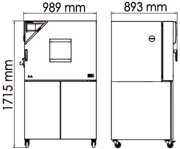
| Depth | 865 mm (MK115-400V) |
| Height | 1725 mm (MK115-400V) |
| Interior height | 480 mm (MK115-400V) |
| Interior width | 600 mm (MK115-400V) |
| Width | 980 mm (MK115-400V) |
| Net weight of the unit (empty) mfr | 255 kg |
| Power frequency | 50 Hz |
| Rated voltage | 400 V |
| Unit fuse | 16.0 A |
| Phase (Nominal voltage) mfr | 3 N/PE |
| Cooling down time from 180°C to -40°C mfr | 90 min |
| Average heating-up rate according to IEC 60068-3-5 between -40°C and 180°C mfr | 5.3 K/min |
Description
Construction and series positioning
The MK 115 uses a 115-litre interior (600 mm wide, 480 mm high) within a 980 mm wide, 865 mm deep, 1725 mm high cabinet, weighing 255 kg empty. It is the smallest MK size that runs on 400 V three-phase supply (3 N/PE, 50 Hz, 16 A fuse, 3.5 kW nominal power) and, unlike the MK 56, carries a rear power switch in addition to the main switch. Within the MK family it sits between the 56-litre entry size and the 240-, 400-, 720- and 1020-litre larger chambers; the CO₂ variants of the 240 and 1020 extend the range downward to -48/-50 °C, which the MK 115 does not offer.
Thermal behaviour
- Working range: -40 to 180 °C.
- Average heating rate per IEC 60068-3-5 between -40 and 180 °C: 5.3 K/min.
- Cooling from 180 °C to -40 °C: 90 min.
- Temperature uniformity: 0.1 to 2.0 K depending on set value; fluctuation 0.1 to 0.5 K.
- Maximum load per rack: 30 kg.
These figures define the chamber as a rapid-change unit rather than a steady-state incubator; the uniformity spread widens with set value, so tight-tolerance work should be planned around the lower end of the range.
Control, safety and installation
Control is via the MB2 chamber controller with fixed-value, timer, time-program and week-program modes, chart-recorder display, Ethernet interface and optional RS485 and analog temperature outputs. Safety is provided by an over-temperature protective device class 1 (trips at nominal +20 °C) and a DIN 12880 class 2.0 temperature safety device; an over/under temperature safety device class 2 is optional. The chamber must be installed with ventilation clearance, away from damp areas and hazardous locations, and connected only by qualified personnel.
Integration & Operating Notes
The MK 115 draws 3.5 kW on a 3 N/PE 400 V 50 Hz supply and requires a 16 A unit fuse. A single-phase or 230 V feed cannot be used; the supply, cabling and over-current protection must be sized for the three-phase load before the chamber is installed.
The manual prohibits installation in unventilated recesses and requires the prescribed minimum distances for heat dispersal. Because the chamber rejects heat during cooling operation, an enclosed or cramped location will cause overheating and possible damage; plan the bench or floor space accordingly.
The chamber has no explosion protection and must not be operated where combustible dust or air-solvent mixtures can form. Charging materials that release flammable vapours at working temperature must be excluded, and the site classification must be checked before installation.
The class 1 protective device responds if the nominal temperature is exceeded by 20 °C due to chamber failure. A trip is not a normal process event: the chamber must be taken out of operation and BINDER Service informed before it is restarted.
After 8760 operating hours or two years the controller displays a maintenance message; confirming it only postpones it, and the window reappears every two weeks until BINDER Service resets the counter. Schedule the service visit before the threshold to avoid recurring interruptions.
An annual repeat electrical inspection is required, plus a test before initial startup and before resuming operation after maintenance or repair, following EN 50678/VDE 0701 and EN 50699/VDE 0702. Build this into the site's safety schedule; the chamber should not be returned to service untested.
Operating personnel may perform only the checks in the simple troubleshooting table, without opening or disassembling the chamber. Detailed diagnosis and repair are reserved for BINDER Service or qualified partners, so a service contract should be in place for fault resolution.
Selection & Integration Q&A
Pick the MK 115 when 115 L of usable volume and a 400 V three-phase supply fit the site; it is the smallest MK with three-phase power and a rear power switch. The MK 56 is 230/240 V single-phase for smaller loads, while the MK 240 offers more volume at the same -40...180 °C range.
A 3 N/PE 400 V 50 Hz feed with a 16 A fuse, sized for the 3.5 kW nominal power. Single-phase 230 V is not acceptable. The chamber must be connected by qualified personnel per the electrical connection chapter, and the supply must be tested before startup.
Install with ventilation clearance, not in unventilated recesses, not in damp areas or puddles, and not in hazardous locations. Maximum load is 30 kg per rack. The chamber must not be operated with a damaged housing or power cord.
Plan annual electrical inspection per EN 50678/VDE 0701 and EN 50699/VDE 0702, and a service reset at 8760 h or two years. Options such as RS485, analog temperature outputs, Pt 100 object sensor, compressed air connection/dryer and APT-COM™ 4 software are not included and must be ordered separately; water cooling is not available for the MK 115.