
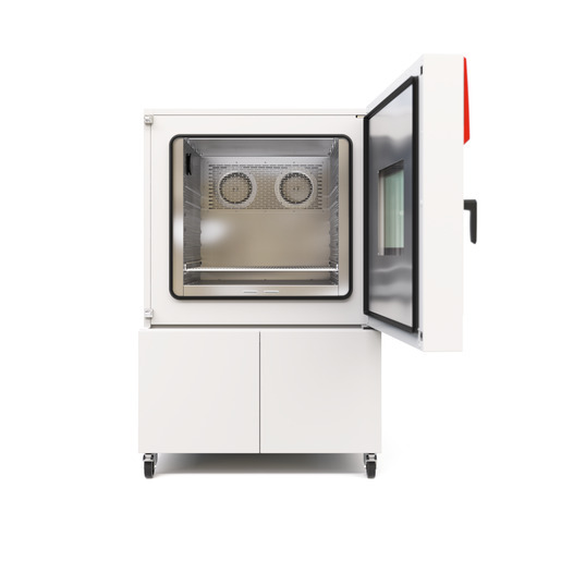
BINDER MK 400 CO₂
BINDER MK 400 CO₂ — Climate chambers.
The BINDER MK 400 CO₂ is a 417 L alternating climate chamber with a CO₂ (R744) refrigeration circuit, rated -50…180 °C and 6.8 kW at 400 V / 3 N/PE / 50 Hz. It is the mid-size 400 L modification of the MK (E6) series, distinguished by its extended low-temperature limit and CO₂ refrigerant. It serves rapid temperature-change testing of components and materials under programmable profiles.
BINDER MK Series — Model Comparison & Selection
| Model | Temperature, °C | Depth, cm | Height, cm | Interior height, mm | Interior volume, L | Interior width, mm |
|---|---|---|---|---|---|---|
| MK 400 CO₂ Current | -50...180 | 140 | 171 | 700 | 417 | 735 |
| MK 1020 | -40–180 | 148 | 200.5 | 1020 | 991 | 1200 |
| MK 1020 CO₂ | -48–180 | 148 | 200.5 | 1020 | 991 | 1200 |
| MK 115 | -40–180 | 86.5 | 172.5 | 480 | 115 | 600 |
| MK 240 | -40–180 | 92.5 | 171 | 700 | 228 | 735 |
| MK 240 CO₂ | -50...180 | 92.5 | 171 | 700 | 228 | 735 |
| MK 400 | -40–180 | 140 | 171 | 700 | 417 | 735 |
| MK 56 | -40–180 | 77.8 | 144.5 | 420 | 60 | 400 |
| MK 720 | -40–180 | 114 | 200.5 | 1020 | 734 | 1200 |
| MK 720 CO₂ | -48–180 | 114 | 200.5 | 1020 | 734 | 1200 |
Full specifications
| Temperature | -50...180 |
| Interior volume | 417 L |
| Load per rack | 30 kg (MK400CO2-400V, 50 Hz) |
| Nominal power | 6.8 kW |
| Article Number mfr | 9020 |
| Depth | 1400 mm (MK400CO2-400V, 50 Hz) |
| Height | 1710 mm (MK400CO2-400V, 50 Hz) |
| Interior height | 700 mm (MK400CO2-400V, 50 Hz) |
| Interior width | 735 mm (MK400CO2-400V, 50 Hz) |
| Width | 1115 mm (MK400CO2-400V, 50 Hz) |
| Net weight of the unit (empty) mfr | 380 kg |
| Power frequency | 50 Hz |
| Rated voltage | 400 V |
| Unit fuse | 16.0 A |
| Phase (Nominal voltage) mfr | 3 N/PE |
| Cooling down time from 180°C to -40°C mfr | 80 min |
| Average heating-up rate according to IEC 60068-3-5 between -40°C and 180°C mfr | 5.7 K/min |
Description
Construction and series positioning
- The MK 400 CO₂ (Art. 9020-0518 for 400 V / 50 Hz) is a floor-standing chamber with 417 L interior volume (735 mm W × 700 mm H) and 380 kg net weight.
- Within the MK (E6) series it sits between the MK 240 and MK 720; unlike the MK 115, MK 240 and MK 1020 (all -40…180 °C), this CO₂ variant reaches -50 °C, and the MK 1020 CO₂ reaches -48 °C.
- Refrigerant is R744 (CO₂), filling weight 1.40 kg, maximum refrigerating-system pressure 120 bar; refrigeration-circuit repairs are currently restricted to BINDER.
Thermal behaviour
- Working range -50…180 °C; temperature uniformity 0.1…1.0 K and fluctuation 0.1…0.4 K, both dependent on set value.
- Average heating rate 5.7 K/min between -40 °C and 180 °C and average cooling rate 5.0 K/min between 180 °C and -40 °C (IEC 60068-3-5); cooling from 180 °C to -40 °C takes 80 min.
- Rack load is limited to 30 kg per rack.
Control, installation and operation
- The MB2 chamber controller provides Fixed Value, timer, time-program and week-program modes with ramp/step setpoints, tolerance ranges, chart-recorder views, user management and alarm/notification handling.
- Over-temperature protection is class 1 plus an over-temperature safety controller class 2; an over/under temperature safety device class 2 is optional.
- Electrical supply is 400 V 3 N/PE 50 Hz, 6.8 kW nominal, 16.0 A unit fuse; operation requires a type B residual current circuit breaker.
- Installation must respect minimum distances, avoid unventilated recesses and damp areas, and the room volume must be calculated per EN 378-1:2016+A1:2020.
Integration & Operating Notes
The chamber may only be operated on a circuit protected by a type B RCD; a type A or AC device does not cover the CO₂ refrigeration drive's fault currents. Verify the site distribution board before commissioning and size the 16.0 A fuse and 6.8 kW load accordingly.
Because the refrigerating circuit holds 1.40 kg of R744 at up to 120 bar, the installation room volume must be calculated according to EN 378-1:2016+A1:2020 before startup. Unventilated recesses and damp areas are prohibited, and prescribed minimum distances must be kept for heat dispersal.
The chamber temperature must remain below the flash point or sublimation point of the load, and no explosive mixture with air may form. Confirm the material's thermal limits against the -50…180 °C working range before programming a profile.
Schedule maintenance at least once a year and an electrical repeat inspection per EN 50678/VDE 0701 and EN 50699/VDE 0702 before initial startup and after any maintenance or repair. Refrigeration work must be logged in a service log book and performed only by EN 13313-trained personnel; circuit repairs currently only at BINDER.
After 8760 operating hours or two years the controller shows a service message; once acknowledged it reappears every two weeks until reset by BINDER Service. Plan the service visit rather than troubleshooting the chamber as if it had failed.
With increased dust in ambient air, inspect the fan grid behind the left maintenance access flap every week and clean by suction if dirty; clean the condenser fan several times a year. Blocked airflow degrades cooling performance and can overheat the refrigerating module.
The door gasket must be changed only when the chamber is cold; fitting it warm risks deformation and loss of sealing. Coordinate gasket replacement with cool-down periods in the test schedule.
Inner surfaces, window, access ports and inner chamber become hot and almost equal the set-point during and shortly after operation. Provide burn protection and allow cool-down before touching; do not load the lower housing cover or climb on it while the door is open.
Selection & Integration Q&A
Pick the MK 400 CO₂ for 417 L of usable volume and a -50 °C low limit; the MK 240 is smaller and stops at -40 °C, while the MK 1020 CO₂ offers more volume but only -48 °C. Choose this model when mid-size batches need the coldest CO₂ operation.
A 400 V 3 N/PE 50 Hz supply rated for 6.8 kW with a 16.0 A unit fuse, protected by a type B residual current circuit breaker. The installation room volume must also be verified per EN 378-1 for the 1.40 kg CO₂ charge.
Do not install in unventilated recesses or damp areas; keep the prescribed minimum distances for heat dispersal and calculate room volume per EN 378-1:2016+A1:2020. IP 20 means no water exposure, and the rear panel must not be removed.
Plan annual maintenance, annual electrical repeat inspection per EN 50678/50699, and weekly condenser fan grid checks in dusty rooms. Options such as RS485, analog temperature outputs, Pt 100 object sensor and APT-COM 4 software are not included in base delivery.