
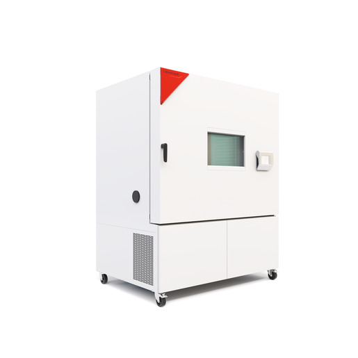
BINDER MK 720 CO₂
BINDER MK 720 CO₂ — Climate chambers with Temperature -48…180 °C.
The MK 720 CO₂ is a 734 L dynamic climate chamber with CO₂ (R744) refrigeration, achieving -48 °C to 180 °C and rapid changes (4.5 K/min heating, 5.7 K/min cooling). Its 400 V 3-phase 8.7 kW design and 16 A fuse distinguish it from smaller MK 240/400 siblings, while the CO₂ suffix denotes extended low-temperature capability versus standard MK 720. It serves as a high-throughput test platform for cyclic temperature stress screening in a ventilated laboratory.
BINDER MK Series — Model Comparison & Selection
| Model | Temperature, °C | Depth, cm | Height, cm | Interior height, mm | Interior volume, L | Interior width, mm |
|---|---|---|---|---|---|---|
| MK 720 CO₂ Current | -48–180 | 114 | 200.5 | 1020 | 734 | 1200 |
| MK 1020 | -40–180 | 148 | 200.5 | 1020 | 991 | 1200 |
| MK 1020 CO₂ | -48–180 | 148 | 200.5 | 1020 | 991 | 1200 |
| MK 115 | -40–180 | 86.5 | 172.5 | 480 | 115 | 600 |
| MK 240 | -40–180 | 92.5 | 171 | 700 | 228 | 735 |
| MK 240 CO₂ | -50...180 | 92.5 | 171 | 700 | 228 | 735 |
| MK 400 | -40–180 | 140 | 171 | 700 | 417 | 735 |
| MK 400 CO₂ | -50...180 | 140 | 171 | 700 | 417 | 735 |
| MK 56 | -40–180 | 77.8 | 144.5 | 420 | 60 | 400 |
| MK 720 | -40–180 | 114 | 200.5 | 1020 | 734 | 1200 |
Full specifications
| Temperature | -48...180 °C |
| Interior volume | 734 L |
| Load per rack | 40 kg (MK720CO2-400V, 50 Hz) |
| Nominal power | 8.7 kW |
| Article Number mfr | 9020 |
| Depth | 1140 mm (MK720CO2-400V, 50 Hz) |
| Height | 2005 mm (MK720CO2-400V, 50 Hz) |
| Interior height | 1020 mm (MK720CO2-400V, 50 Hz) |
| Interior width | 1200 mm (MK720CO2-400V, 50 Hz) |
| Width | 1580 mm (MK720CO2-400V, 50 Hz) |
| Net weight of the unit (empty) mfr | 495 kg |
| Power frequency | 50 Hz |
| Rated voltage | 400 V |
| Unit fuse | 16.0 A |
| Phase (Nominal voltage) mfr | 3 N/PE |
| Cooling down time from 180°C to -40°C mfr | 60 min |
| Average heating-up rate according to IEC 60068-3-5 between -40°C and 180°C mfr | 4.5 K/min |
Description
Construction and series positioning
- The MK 720 CO₂ (E6 series) is a floor-standing alternating climate chamber with 734 L interior volume (1200 mm W × 1020 mm H × 1140 mm D) and 495 kg net weight.
- CO₂ (R744) refrigerant circuit operates at up to 120 bar; refrigeration repairs are restricted to BINDER.
- Within the MK series, the CO₂ variant extends the lower temperature limit to -48 °C, whereas standard MK 240/400/720/1020 models reach -40 °C. The 720 size sits between the 240/400 and 1020 siblings, offering 40 kg per rack load.
Thermal behavior and modes
- Temperature range -48…180 °C; uniformity 0.1…1.0 K and fluctuation 0.1…0.2 K depending on setpoint.
- Average heating rate 4.5 K/min (-40→180 °C) and cooling rate 5.7 K/min (180→-40 °C) per IEC 60068-3-5; full 180→-40 °C cool-down in 60 min.
- MB2 controller supports fixed-value, time-program, and week-program modes with ramp/step setpoints and tolerance ranges.
Installation, control, and operation
- Requires 400 V 3 N/PE 50 Hz supply, 8.7 kW nominal power, 16 A unit fuse; residual current device type B mandatory.
- IP20 protection; must not be installed in unventilated recesses or damp areas; room volume per EN 378-1:2016+A1:2020.
- Control terminal ergonomically adjustable; rear panel must not be removed; chamber must not become wet.
- Annual maintenance and electrical repeat inspection required; service message after 8760 h or two years.
Integration & Operating Notes
The chamber must be operated only with residual current circuit breakers type B. The site electrical installation must provide a 400 V 3 N/PE 50 Hz supply with 16 A overcurrent protection and a type B RCD; other RCD types may not detect DC fault currents from the CO₂ refrigeration drive.
The installation room volume must be calculated according to EN 378-1:2016+A1:2020 to ensure safe dispersion of 1.40 kg CO₂ refrigerant in case of leakage. Do not install in unventilated recesses or damp areas; prescribed minimum distances must be observed for heat dispersal.
The temperature inside the chamber must lie below the flash point or sublimation point of the charging material, and no explosive mixture with air may form. Verify material properties before setting operating temperature; inner surfaces, window, and access ports become hot during operation.
Maintenance work at least once a year; electrical repeat inspection required annually and before initial startup and after maintenance or repair (EN 50678/VDE 0701, EN 50699/VDE 0702). Refrigeration system work only by qualified personnel per EN 13313:2010 and documented in a service log book.
After 8760 operating hours or two years a service message appears; after confirmation it reappears every two weeks until reset by BINDER Service. This is a time-based reminder, not a fault; only BINDER Service can reset it.
With increased dust in ambient air, clean the condenser fan several times a year; check the fan grid behind the left maintenance access flap every week and clean by suction if dirty. Replace door gasket only when cold to avoid damage.
The chamber must not become wet during operation, cleaning, or maintenance; do not remove the rear panel. Cleaning and maintenance procedures must avoid water ingress; rear panel removal is prohibited. IP20 protection means no water protection.
Selection & Integration Q&A
Choose MK 720 CO₂ when you need -48 °C lower limit and 734 L capacity with 40 kg/rack load. The standard MK 720 stops at -40 °C; the MK 1020 CO₂ offers more volume but higher power and footprint. Select MK 720 CO₂ for mid-size high-throughput cycling.
Requires 400 V 3 N/PE 50 Hz supply, 8.7 kW nominal power, 16 A unit fuse, and a type B residual current circuit breaker. Verify room volume per EN 378-1 for CO₂ refrigerant and provide minimum clearances for heat dispersal.
Install in a ventilated, non-damp area with room volume calculated per EN 378-1:2016+A1:2020; do not install in unventilated recesses. IP20 protection prohibits water exposure. Annual maintenance and electrical repeat inspection are mandatory; service message after 8760 h or two years.
Annual maintenance by qualified personnel (EN 13313:2010 for refrigeration) and annual electrical repeat inspection per EN 50678/VDE 0701. Options include RS485 interface, zero-voltage switching outputs, analog temperature outputs, Pt 100 sensor, over/under temperature safety device class 2, and APT-COM 4 software; these are not included in base delivery.