
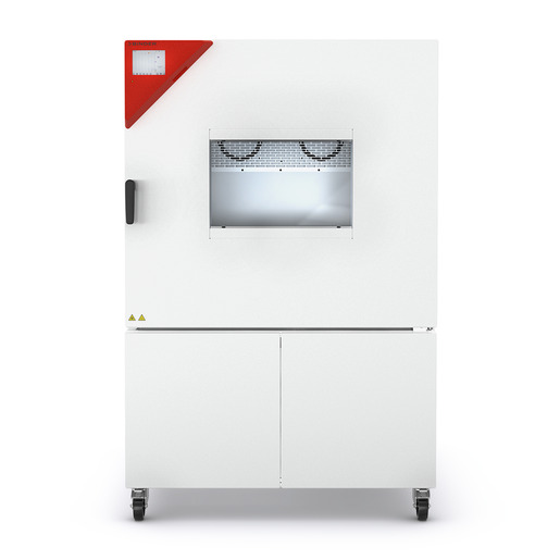
BINDER MK 400
BINDER MK 400 — Climate chambers with Temperature -40…180 °C.
The BINDER MK 400 is a 417-litre dynamic climate chamber with a -40 to 180 °C working range and a 7 kW heating/cooling system, built for rapid temperature cycling. It is the mid-size 400 V three-phase model in the MK series, distinguished from the 115 and 240 by chamber volume and from the 1020 by capacity. It serves as a test platform for accelerated thermal stress and material qualification.
BINDER MK Series — Model Comparison & Selection
| Model | Temperature, °C | Depth, cm | Height, cm | Interior height, mm | Interior volume, L | Interior width, mm |
|---|---|---|---|---|---|---|
| MK 400 Current | -40–180 | 140 | 171 | 700 | 417 | 735 |
| MK 1020 | -40–180 | 148 | 200.5 | 1020 | 991 | 1200 |
| MK 1020 CO₂ | -48–180 | 148 | 200.5 | 1020 | 991 | 1200 |
| MK 115 | -40–180 | 86.5 | 172.5 | 480 | 115 | 600 |
| MK 240 | -40–180 | 92.5 | 171 | 700 | 228 | 735 |
| MK 240 CO₂ | -50...180 | 92.5 | 171 | 700 | 228 | 735 |
| MK 400 CO₂ | -50...180 | 140 | 171 | 700 | 417 | 735 |
| MK 56 | -40–180 | 77.8 | 144.5 | 420 | 60 | 400 |
| MK 720 | -40–180 | 114 | 200.5 | 1020 | 734 | 1200 |
| MK 720 CO₂ | -48–180 | 114 | 200.5 | 1020 | 734 | 1200 |
Full specifications
| Temperature | -40...180 °C |
| Interior volume | 417 L |
| Load per rack | 30 kg (MK400-400V and MK400-480V-C) |
| Nominal power | 7 kW |
| Article Number mfr | 9020 |
| Depth | 1400 mm (MK400-400V and MK400-480V-C) |
| Height | 1710 mm (MK400-400V and MK400-480V-C) |
| Interior height | 700 mm (MK400-400V and MK400-480V-C) |
| Interior width | 735 mm (MK400-400V and MK400-480V-C) |
| Width | 1115 mm (MK400-400V and MK400-480V-C) |
| Net weight of the unit (empty) mfr | 413 kg |
| Power frequency | 50 Hz |
| Rated voltage | 400 V |
| Unit fuse | 16.0 A |
| Phase (Nominal voltage) mfr | 3 N/PE |
| Cooling down time from 180°C to -40°C mfr | 115 min |
| Average heating-up rate according to IEC 60068-3-5 between -40°C and 180°C mfr | 5.0 K/min |
Description
Construction and series positioning
The MK 400 is a floor-standing dynamic climate chamber with 417 L usable interior volume (735 mm wide × 700 mm high × 1,400 mm deep) and a net weight of 413 kg. Within the MK series it sits between the 240 and 1020 sizes; unlike the smaller MK 115 and MK 240, it is supplied only in 400 V three-phase configuration. The standard variant is MK400-400V (Art.-No. 9020-0406); the -C variant adds a voltage and frequency changer for 480 V 60 Hz sites. Rack loading is limited to 30 kg per rack.
Thermal behaviour
- Working range: -40 to 180 °C.
- Average heating rate per IEC 60068-3-5 between -40 and 180 °C: 5.0 K/min.
- Cooling from 180 to -40 °C: 115 min.
- Temperature uniformity: 0.1 to 1.2 K depending on set value; fluctuation 0.1 to 0.5 K.
These figures define the achievable ramp and soak performance; the cooling-down time is the dominant constraint for full-range cycling, while uniformity and fluctuation govern the usable test tolerance band.
Electrical and control architecture
The chamber requires a 3 N/PE 400 V 50 Hz supply with a 16 A unit fuse and 7 kW nominal power. Control is via the MB2 chamber controller with fixed-value, time-program and week-program modes, a chart-recorder display, Ethernet and optional RS485/analog interfaces. Safety is provided by an over-temperature protective device class 1 and a DIN 12880 class 2.0 temperature safety device; an optional over/under temperature safety device class 2 is available.
Installation and operation
Installation must avoid unventilated recesses and observe minimum distances for heat dispersal; the chamber must not be installed in damp areas or hazardous locations. The rear power switch is fitted from size 115 upward. Maintenance messages appear after 8760 operating hours or two years, and an annual electrical inspection per EN 50678/VDE 0701 and EN 50699/VDE 0702 is required.
Integration & Operating Notes
The 7 kW nominal load and 16 A unit fuse require a dedicated three-phase feed sized for the chamber; the -C variant instead uses a 480 V 60 Hz supply through its voltage and frequency changer, which has its own connection procedure. Undersized feeds or missing neutral will prevent correct operation.
Heat dispersal from the refrigeration system requires sufficient ventilation and the prescribed minimum distances from walls and adjacent equipment. Enclosing the 413 kg unit in a closed recess will cause overheating and can damage the chamber; plan the floor position accordingly.
The chamber has no explosion protection measures and must not be operated where combustible dust or air-solvent mixtures can be present. Charging materials that release flammable vapours at working temperature must be excluded from the test plan.
The over-temperature protective device class 1 responds if the nominal temperature is exceeded by 20 °C due to chamber failure. A class 1 trip is not a normal process event: the chamber must be taken out of operation and BINDER Service informed before restart.
After 8760 operating hours or two years the controller displays a maintenance message; confirming it only postpones the reminder, which reappears every two weeks until BINDER Service resets the counter. Schedule service before the threshold to avoid recurring interruptions.
An annual repeat electrical inspection per EN 50678/VDE 0701 and EN 50699/VDE 0702 is required, plus a test before initial startup and before resuming operation after any maintenance or repair. Only BINDER Service or qualified partners may perform detailed troubleshooting and repair.
The chamber includes an Ethernet serial interface for networking with APT-COM™ 4 software, which is an accessory requiring registration. RS485 and analog temperature outputs are optional and must be specified at ordering, as are the Pt 100 object sensor and compressed air connection.
Selection & Integration Q&A
Pick the MK 400 when 417 L of usable volume fits the batch and the 5.0 K/min heating rate and 115 min full-range cooling suit the cycle. The MK 240 offers less volume; the MK 1020 offers more and is the only size besides MK 56 with water cooling. The MK 400 has no water-cooling option.
The standard MK400-400V requires 400 V 3 N/PE 50 Hz, 7 kW nominal, 16 A unit fuse. The -C variant adds a voltage and frequency changer for 480 V 60 Hz sites; its installation and connection follow separate instructions in chapters 4.3 and 4.4.2 and must be planned in addition to the chamber feed.
Install with sufficient ventilation and the prescribed minimum distances; unventilated recesses, damp areas or puddles, hazardous locations and explosive atmospheres are excluded. The chamber must not get wet during operation, cleaning or maintenance, and a damaged housing or power cord puts it out of service.
Base delivery excludes APT-COM™ 4 software, RS485 interface, analog temperature outputs, flexible Pt 100 object sensor, compressed air connection and dryer, and the over/under temperature safety device class 2. Plan the 8760 h / two-year service reset and annual electrical inspection separately.