
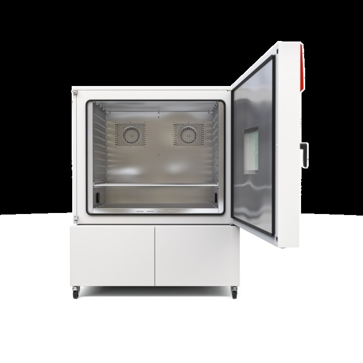
BINDER MK 1020 CO₂
BINDER MK 1020 CO₂ — Climate chambers with Temperature -48…180 °C.
The MK 1020 CO₂ is a 991 L dynamic climate chamber with a -48…180 °C working range, extending the MK 1020's lower limit by 8 K. It is the largest CO₂-refrigerant MK size, drawing 9.6 kW at 400 V/50 Hz with a 3×32 A over-current release. It serves rapid temperature-change testing of harmless solid, pulverized or bulk material under program control.
BINDER MK Series — Model Comparison & Selection
| Model | Temperature, °C | Depth, cm | Height, cm | Interior height, mm | Interior volume, L | Interior width, mm |
|---|---|---|---|---|---|---|
| MK 1020 CO₂ Current | -48–180 | 148 | 200.5 | 1020 | 991 | 1200 |
| MK 1020 | -40–180 | 148 | 200.5 | 1020 | 991 | 1200 |
| MK 115 | -40–180 | 86.5 | 172.5 | 480 | 115 | 600 |
| MK 240 | -40–180 | 92.5 | 171 | 700 | 228 | 735 |
| MK 240 CO₂ | -50...180 | 92.5 | 171 | 700 | 228 | 735 |
| MK 400 | -40–180 | 140 | 171 | 700 | 417 | 735 |
| MK 400 CO₂ | -50...180 | 140 | 171 | 700 | 417 | 735 |
| MK 56 | -40–180 | 77.8 | 144.5 | 420 | 60 | 400 |
| MK 720 | -40–180 | 114 | 200.5 | 1020 | 734 | 1200 |
| MK 720 CO₂ | -48–180 | 114 | 200.5 | 1020 | 734 | 1200 |
Full specifications
| Temperature | -48...180 °C |
| Interior volume | 991 L |
| Load per rack | 40 kg (MK1020CO2-400V, 50 Hz) |
| Nominal power | 9.6 kW |
| Article Number mfr | 9020 |
| Depth | 1480 mm (MK1020CO2-400V, 50 Hz) |
| Height | 2005 mm (MK1020CO2-400V, 50 Hz) |
| Interior height | 1020 mm (MK1020CO2-400V, 50 Hz) |
| Interior width | 1200 mm (MK1020CO2-400V, 50 Hz) |
| Width | 1580 mm (MK1020CO2-400V, 50 Hz) |
| Net weight of the unit (empty) mfr | 556 kg |
| Power frequency | 50 Hz |
| Rated voltage | 400 V |
| Unit fuse | 32.0 A |
| Phase (Nominal voltage) mfr | 3 N/PE |
| Cooling down time from 180°C to -40°C mfr | 70 min |
| Average heating-up rate according to IEC 60068-3-5 between -40°C and 180°C mfr | 6.2 K/min |
Description
Construction and series positioning
- 991 L interior (1200 × 1020 mm W×H), 1580 × 2005 × 1480 mm net envelope, 556 kg empty.
- CO₂ refrigerant variant: lower limit -48 °C versus -40 °C on the standard MK 1020; the MK 240 CO₂ reaches -50 °C but is a smaller size.
- Fixed power cable ≥1800 mm; operating panel on the left chamber side; refrigeration/maintenance access flaps on the MK body.
- Temperature safety device class 2 (upper J1 / lower J2 limits) is an option, not base equipment.
Thermal behavior
- Average heating rate 6.2 K/min (-40 → 180 °C) and cooling rate 4.8 K/min (180 → -40 °C) per IEC 60068-3-5; full 180 → -40 °C cooldown takes 70 min.
- Uniformity 0.1…1.0 K and fluctuation 0.1…0.2 K, both set-value dependent — tight control at moderate setpoints, wider spread near the extremes.
- Rack load limited to 40 kg per rack; the 70 min cooldown and 6.2 K/min ramp define realistic profile cycle times.
Electrical and installation
- 400 V 3N/PE 50 Hz, 9.6 kW, 22.30 A, 3×32 A over-current release (Art. 9020-0527); the 480 V/60 Hz variant (9020-0529) uses 3×25 A at 17.60 A.
- Type B RCD required; pollution degree 2, over-voltage category II, IP 20 — indoor dry locations only.
- CO₂ refrigerant: room volume per EN 378-1 and a CO₂ warning system are recommended; no non-ventilated recesses.
Integration & Operating Notes
The 50 Hz MK 1020 CO₂ draws 22.30 A at 9.6 kW; size the supply and the 3-pole over-current release for 3×32 A. Undersizing the release or sharing protection with other chambers risks nuisance tripping during compressor start and invalidates the installation.
The chamber's electronics and CO₂ refrigeration drive require type B RCDs; type A or AC devices may not detect the DC residual component. Provide current protection matched to the number of chambers on the circuit, and verify supply voltage and frequency against the type plate before first start-up.
CO₂ is the refrigerant; calculate the required room volume per EN 378-1:2016+A1:2020 and install a CO₂ warning system where recommended. Do not place the unit in non-ventilated recesses; provide technical ventilation or an exhaust connection. IP 20 and pollution degree 2 restrict it to dry indoor sites protected from splashing.
Programmed temperature must remain below the flash point or sublimation point of the charging material, and no component may release toxic gases. Exclude acids and halides that attack stainless steel, aluminum and copper. Respect the 40 kg per-rack limit when arranging the 991 L interior.
Zero-voltage alarm contacts are rated 24 V AC/DC, 2.5 A maximum switching load. Connecting higher-load devices damages the contacts and socket and creates a shock hazard. The two zero-voltage switching outputs are an option on MK models — specify at ordering if alarm relays or the analog temperature output are needed.
The refrigeration machine and maintenance access flaps sit on the chamber body; keep clearance for service access and do not block them. The fixed power cable is at least 1800 mm long, so position the unit so the plug remains easily accessible for emergency disconnection without an extension cord.
Selection & Integration Q&A
Pick the MK 1020 CO₂ when you need the 991 L interior and testing down to -48 °C. The standard MK 1020 stops at -40 °C; the MK 240 CO₂ reaches -50 °C but offers a much smaller chamber. Choose by volume first, then by lower temperature limit.
400 V 3N/PE 50 Hz, 9.6 kW, 22.30 A, protected by a 3-pole 32 A over-current release and a type B RCD. Verify voltage and frequency against the type plate; the 60 Hz variant (9020-0529) instead needs 480 V and a 3×25 A release.
Indoor dry location only: IP 20, pollution degree 2, over-voltage category II. Because CO₂ is the refrigerant, calculate room volume per EN 378-1 and avoid non-ventilated recesses; provide ventilation or an exhaust connection and keep the refrigeration access flaps clear.
The temperature safety device class 2 (J1/J2 limits), the two zero-voltage switching outputs and the analog temperature output are options on MK models and must be ordered. The fixed power cable is included (≥1800 mm), but no external alarm wiring or extension is supplied.