
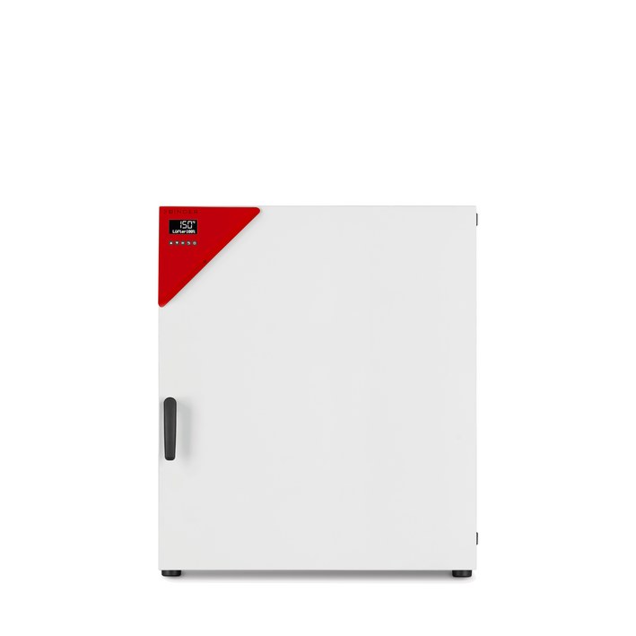
BINDER FED 260
BINDER FED 260 — Drying ovens with Temperature 10…300 °C.
The FED 260 is a forced-convection drying and heating oven with a 259 L interior, adjustable fan speed in 10% steps, and a 10–300 °C working range. Within the FED series it is the mid-size 260 variant (230 V, 2.3 kW, 12.5 A external fuse), distinguished from the 56/115 sizes by capacity and from the 720 by single-phase supply. It serves precise tempering, drying, and heat treatment of solid or bulk materials where homogeneous airflow and timer/ramp functions are required.
BINDER FED Series — Model Comparison & Selection
Full specifications
| Temperature | 10...300 °C |
| Air change rate | 9 x/h |
| Heating time to 150°C | 19 min |
| Interior volume | 259 L |
| Load per rack | 40 kg (FED260-230V / FED260UL-240V) |
| Nominal power | 2.3 kW |
| Permitted load | 270 kg (FED260-230V / FED260UL-240V) |
| Temperature fluctuation | 0.4 K |
| Temperature uniformity | 1.6 K |
| Rear wall clearance | 160 mm (FED260-230V / FED260UL-240V) |
| Side wall clearance | 100 mm (FED260-230V / FED260UL-240V) |
| Article Number mfr | 9010 |
| Recovery time after door was opened for 30 s at 150°C mfr | 5 min |
| Depth | 760 mm (FED260-230V / FED260UL-240V) |
| Height | 940 mm (FED260-230V / FED260UL-240V) |
| Width | 810 mm (FED260-230V / FED260UL-240V) |
| Net weight of the unit (empty) mfr | 85 kg |
| Power frequency | 50 Hz |
| Rated voltage | 230 V |
| Unit fuse | 12.5 A |
| Phase (Nominal voltage) mfr | 1 |
Description
Construction and series positioning
- Forced-convection (fan-assisted) oven with enhanced timer functions (Delayed On/Off, temperature-dependent Delayed Off) and standard Ethernet interface; differs from FD by the timer/ramp feature set and from ED by active air circulation.
- 259 L interior (810 × 940 × 760 mm net W×H×D), 85 kg empty, 270 kg permitted load, 40 kg per rack.
- Single-phase 230 V, 50 Hz, 2.3 kW, 12.5 A external chamber fuse; IEC connector with shockproof plug (not the fixed cable of size 720).
- Sits between FED 115 and FED 400 in volume; the 720 is the only FED requiring 400 V 3N~ and an internal 16 A breaker.
Thermal behavior
- Working range 10–300 °C; heating to 150 °C in 19 min; recovery after 30 s door opening at 150 °C in 5 min.
- Temperature fluctuation 0.4 K, uniformity 1.6 K — figures that depend on respecting the usable-volume rule (≥10% wall clearance, ≤50% loading).
- Fan speed adjustable in 10% increments to trade airflow against sample disturbance; display resolution 1 °C (oven-class controller).
- Overtemperature protection: class 1 device trips at 330 °C for FED 260; safety controller settable 10–300 °C, to be placed 2–5 °C above the working set-point.
Installation, control and operation
- Indoor, non-flammable surface, ambient 18–40 °C, ≤70% r.h. non-condensing, altitude ≤2000 m, supply within ±10%; wall clearances 160 mm rear and 100 mm side.
- R4 controller with ramp function, timer programming, USB data recording, and Ethernet (standard on FED) for network configuration; external devices on USB/Ethernet must comply with EN 61010-1:2010 or EN 60950-1:2006.
- Hot-air sterilization possible at 190 °C for ≥30 min after removing all flammable goods; racks removable and autoclavable.
Integration & Operating Notes
The 2.3 kW heating load and 12.5 A external fuse leave little margin; voltage outside ±10% is a listed cause of malfunction and can prevent the chamber from reaching 300 °C. Verify the type plate against the actual supply before connection and size the upstream circuit for 12.5 A time-lag.
The forced-convection fan draws and returns air through the rear wall; blocking these clearances degrades the 1.6 K uniformity and can overheat the chamber. Install indoors on a non-flammable surface, not in an unventilated recess, at 18–40 °C ambient and ≤70% r.h. non-condensing.
Samples placed closer than 10% of the interior dimensions to the walls, or loading beyond 50% of the usable volume, prevent sufficient airflow and destroy temperature homogeneity. The 40 kg per-rack and 270 kg total limits are absolute; distribute loads evenly across racks.
The chamber must be maintained at least once a year by licensed electricians or BINDER-authorized personnel; unauthorized maintenance voids warranty. Repeat electrical inspection per EN 50678/VDE 0701 and EN 50699/VDE 0702 is required annually and after any repair. Replace the door gasket only when cold.
The chamber has no explosion protection; combustible or explosive substances, dust, or air-solvent mixtures must not be introduced, and the operating temperature must remain below the flash or sublimation point of the charge. Corrosive acids and halides that attack stainless steel, aluminum, or copper are also excluded.
Selection & Integration Q&A
Pick the 260 for 259 L of usable volume with single-phase 230 V supply and 2.3 kW. The 115 is smaller but same voltage; the 400 offers more volume but check its supply; the 720 needs 400 V 3N~ and an internal 16 A breaker, so only choose it if three-phase power is available.
A 230 V 1~ 50 Hz supply within ±10%, protected by a 12.5 A time-lag (T) 5×20 mm / 250 V external chamber fuse. The chamber uses an IEC connector with shockproof plug (CEE 7/7), not a fixed cable; use only original BINDER connection cables.
Install indoors on a non-flammable surface at 18–40 °C and ≤70% r.h. non-condensing, below 2000 m altitude, with 160 mm rear and 100 mm side clearance. Load ≤50% of usable volume with ≥10% wall clearance; total load ≤270 kg, ≤40 kg per rack.
Annual maintenance and electrical inspection per EN 50678/VDE 0701 are required but not included. Optional accessories include APT-COM 4 software, Pt100 object-temperature sensor, analog output, HEPA fresh-air filter, and inert-gas connection with gas-tight version. Neutral cleaner 1002-0016 and disinfectant 1002-0022 are ordered separately.