
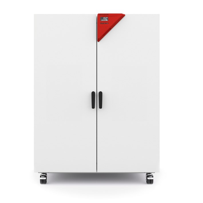
BINDER FED 720
BINDER FED 720 — Drying ovens with Temperature 12…300 °C.
The FED 720 is a forced-convection drying and heating oven with enhanced timer functions, offering 741 L interior volume and a +12 to 300 °C working range. As the largest FED series model, it is the only size with a 400 V 3N~ supply, internal 16 A breaker, and rear main power switch. It is intended for precise tempering, drying, and heat treatment of solid, pulverized, or bulk materials in industrial and laboratory processes.
BINDER FED Series — Model Comparison & Selection
Full specifications
| Temperature | 12...300 °C |
| Air change rate | 5 x/h |
| Heating time to 150°C | 25 min |
| Interior volume | 741 L |
| Load per rack | 45 kg (FED720-400V / FED720UL-208V) |
| Nominal power | 4.5 kW |
| Permitted load | 315 kg (FED720-400V / FED720UL-208V) |
| Temperature fluctuation | 0.6 K |
| Temperature uniformity | 2.0 K |
| Rear wall clearance | 160 mm (FED720-400V / FED720UL-208V) |
| Side wall clearance | 100 mm (FED720-400V / FED720UL-208V) |
| Article Number mfr | 9010 |
| Recovery time after door was opened for 30 s at 150°C mfr | 6 min |
| Depth | 870 mm (FED720-400V / FED720UL-208V) |
| Height | 1590 mm (FED720-400V / FED720UL-208V) |
| Width | 1165 mm (FED720-400V / FED720UL-208V) |
| Net weight of the unit (empty) mfr | 166 kg |
| Power frequency | 50 Hz |
| Rated voltage | 400 V |
| Unit fuse | 16.0 A |
| Phase (Nominal voltage) mfr | 3 N/PE |
Description
Construction and series positioning
- The FED 720 is the size-720 member of the FED series (forced convection, enhanced timer functions), distinct from smaller siblings FED 56, FED 115, FED 260, and FED 400, which operate on 230 V single-phase and have lower nominal power.
- This model uses a 400 V 3N~ supply (50 Hz, 4.5 kW nominal power) with a fixed power cable of at least 1800 mm and an internal 16 A miniature circuit breaker; the main power switch is located on the rear panel.
- Interior volume is 741 L, with net dimensions 1165 mm wide × 1590 mm high × 870 mm deep. Maximum load per rack is 45 kg, total permitted load 315 kg.
- Unlike smaller FED sizes, the maximum adjustable temperature set-point on this two-door chamber depends on ambient temperature.
Behavior under load and in operation
- Temperature range is +12 to 300 °C, with temperature fluctuation of 0.6 K and uniformity of 2.0 K. Heating-up time to 150 °C is 25 minutes; recovery time after a 30-second door opening at 150 °C is 6 minutes.
- Fan speed is adjustable in 10 % steps, allowing airflow and temperature uniformity to be balanced for different load types.
- The chamber is equipped with an overtemperature protective device class 1 (trip temperature 330 °C for FED 720) and a safety controller (class 2 or 3.1). The safety controller set-point range is 10 °C to 300 °C with 1-degree accuracy, and should be set 2–5 °C above the working set-point.
- Loading must leave at least 10 % of interior dimensions as wall clearance and must not exceed half of the usable volume to maintain homogeneous temperature.
Installation, control, and operation
- Installation requires indoor location on a non-flammable surface with minimum wall clearances: 160 mm at the rear and 100 mm at the sides. Permissible ambient temperature is +18 to +40 °C, humidity ≤70 % r.h. non-condensing, and altitude ≤2000 m.
- The R4 controller provides set-point entry for temperature and fan speed, timer functions (Delayed Off, Temperature-dependent Delayed Off, Delayed On), ramp function, and USB data recording. Ethernet interface is standard on FED models.
- Electrical supply must be within ±10 % of nominal voltage. The chamber has IP 20 protection and pollution degree 2 / over-voltage category II per IEC 61010-1.
- For maintenance, the chamber requires annual servicing and electrical safety testing per EN 50678/VDE 0701 and EN 50699/VDE 0702. The door gasket must be replaced only when cold.
Integration & Operating Notes
The FED 720 must be connected to a 400 V 3N~/PE 50 Hz supply with a CEE 16/6 H 5-pin plug. The internal miniature circuit breaker is rated 16 A; upstream protection and cable sizing must account for the 4.5 kW nominal power and ±10 % voltage tolerance. A wrong voltage is a listed cause of malfunction.
Insufficient clearance restricts airflow and can cause overheating or uneven temperature distribution. The chamber must be installed indoors on a non-flammable surface, not in unventilated recesses, and with ambient temperature between +18 and +40 °C and humidity ≤70 % r.h. non-condensing.
Samples must remain inside the usable volume with at least 10 % of interior dimensions as clearance from walls. Overloading prevents sufficient airflow and homogeneous temperature, directly affecting uniformity (2.0 K) and recovery performance.
The safety controller acts as an absolute maximum limit. After any change to the temperature set-point, the safety controller set-point must be re-checked and adjusted to 2–5 °C above it. The permissible range is 10 °C to 300 °C with 1-degree accuracy.
The chamber must be maintained at least once a year by licensed electricians or BINDER-authorized experts. An annual repeat electrical inspection per EN 50678/VDE 0701 and EN 50699/VDE 0702 is required, as well as testing before initial startup and after any maintenance or repair. Warranty is void if maintenance is performed by non-authorized personnel.
Selection & Integration Q&A
Choose the FED 720 when you need 741 L interior volume, 315 kg total load capacity, and 45 kg per rack. It is the only FED size with a 400 V 3N~ supply and internal 16 A breaker. Smaller models (FED 56/115/260/400) use 230 V single-phase and offer less volume and load capacity.
The FED 720 requires a 400 V 3N~/PE 50 Hz supply with a CEE 16/6 H 5-pin plug, nominal power 4.5 kW, and an internal 16 A miniature circuit breaker. Supply voltage must be within ±10 % of nominal. A fixed power cable of at least 1800 mm is provided; plan the installation position accordingly.
Install indoors on a non-flammable surface with ambient temperature +18 to +40 °C, humidity ≤70 % r.h. non-condensing, and altitude ≤2000 m. Maintain at least 160 mm rear and 100 mm side wall clearance. Do not install in unventilated recesses or explosive areas.
Annual maintenance by authorized personnel and annual electrical safety testing per EN 50678/VDE 0701 and EN 50699/VDE 0702 are required. Recommended cleaning agents are neutral cleaner art. no. 1002-0016 and disinfectant spray art. no. 1002-0022. Optional accessories include APT-COM 4 software, Pt100 sensor, analog output, HEPA fresh air filter, and inert gas connection.