
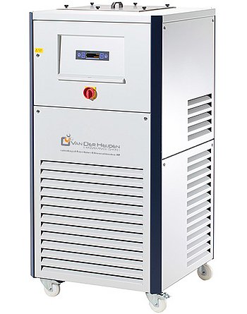
Peter Huber Kältemaschinenbau CS 50 by Van der Heijden
Peter Huber Kältemaschinenbau CS 50 by Van der Heijden — Recirculating chillers with Noise level 63 dB.
The CS 50 by Van der Heijden is a 37-litre-bath recirculating chiller with a -20…15 °C working range, positioned as the smallest unit in the Cs Chiller series. It is distinguished by a 70 l/min pressure pump (max 3.7 bar) and a 100–110 l minimum filling capacity, making it suitable for cooling external process loops rather than small analytical baths.
Peter Huber Kältemaschinenbau Cs Chiller Series — Model Comparison & Selection
| Model | Noise level, dB | Ambient temperature limit, °C | Minimum fill volume, m³ | Power supply | Pump connection | Temperature range, °C |
|---|---|---|---|---|---|---|
| CS 50 by Van der Heijden Current | 63 | 5–32 | 0.1 | 400V 3~ 50Hz | G3/4 AG male | -20–15 |
| CS 100 by Van der Heijden | 70 | 5–32 | 0.16 | 400V 3~ 50Hz | G3/4 AG male | -20–15 |
| CS 100-H by Van der Heijden | 71 | 5–32 | 0.175 | 400V 3~ 50Hz | G3/4 AG male | -20–85 |
| CS 200 by Van der Heijden | 78 | 5–32 | 0.225 | 400V 3~ 50Hz | G1 AG male | -20–15 |
| CS 200-H by Van der Heijden | 78 | 5–32 | 0.225 | 400V 3~ 50Hz | G1 AG male | -20–85 |
| CS 20-H by Van der Heijden | 57 | 5–32 | 0.024 | 230V 1~ 50Hz | G3/8 AG male | -20–85 |
| CS 25 by Van der Heijden | 60 | 5–32 | 0.024 | 230V 1~ 50Hz | G1/2 AG male | -20–15 |
| CS 75 by Van der Heijden | 66 | 5–32 | 0.16 | 400V 3~ 50Hz | G3/4 AG male | -20–15 |
| Huber CS 200-H | 78 | 5–32 | 0.225 | 460V 3~ 60Hz | G1 AG male | -20–85 |
| Huber CS 25 | 60 | 5–32 | 0.024 | 208V 2~ 60Hz | G1/2 AG male | -20–15 |
| Huber CS 250HT OD | 78 | -20–50 | 0.16 | 460V 3~ 60Hz | G3/4 AG male | 10–22 |
| Huber CS 330-H OD | 78 | -20–50 | 0.16 | 460V 3~ 60Hz | G1 AG male | -20–85 |
| Huber CS 550-H OD | 79 | -20–50 | 0.16 | 460V 3~ 60Hz | G1 AG male | -20–85 |
| Huber CS 550 OD | 79 | -20–50 | 0.16 | 460V 3~ 60Hz | G1 AG male | -20–15 |
| Huber LCS 80 | 77 | -20–50 | 0.04 | 460V 3~ 60Hz | G1 AG male | -45–15 |
Full specifications
| Noise level | 63 dB(A) |
| Bath volume | 37 l |
| Maximum delivery flow rate | 70 l/min (pressure pump max 3, 7 bar) |
| Minimum fill volume | 100 l |
| Pump connection | G3/4 AG male |
| Temperature range | -20...15 °C |
| Weight | 199 kg |
| Current consumption | 9 A (max) |
| Power supply | 400V 3~ 50Hz |
| Ambient temperature limit | 5...32 °C |
| Protection rating | IP52 |
| Safety class | I / NFL |
Description
Construction and series positioning
- The CS 50 is the base model of the Cs Chiller series; siblings CS 100, CS 100-H, CS 125 and CS 125-H step up in capacity and noise level (63 dB(A) here vs 70–75 dB(A) for the larger units).
- It uses a 37 l internal bath but requires a minimum filling capacity of 100 l (max 110 l), indicating the working volume is dominated by the external application loop rather than the bath itself.
- Refrigerant is R-449A (A1, H280); the unit is EMC-classified Class A, Group 1 to EN55011 and certified for US-SNAP industrial process refrigeration.
Working range and media
- Temperature range is -20…15 °C, so the unit is a low-temperature chiller, not a heating thermostat.
- Recommended heat-transfer fluid is a 50:50 water–monoethylene glycol mixture, consistent with the sub-zero range.
- Cooling capacity is rated at 20 °C ambient and drops as ambient temperature rises; size with margin for the actual room temperature.
- Flow rate is adjustable via a manual bypass valve on the rear of the chiller, allowing matching to the application's pressure drop.
Installation and operation
- Power supply is 400 V 3~ 50 Hz with a 3×16 A fuse required at the installation site; maximum current consumption is 9 A.
- Three-phase devices below 63 A are delivered with cable but without plug, so the installer must provide a suitable plug.
- Voltage and frequency tolerances must be respected simultaneously; a -5% voltage combined with +2% frequency is not allowed.
- Pump connection is G3/4 AG male; protection rating is IP52; weight is 199 kg.
- Ambient temperature must stay between 5 °C and 32 °C; space requirements around the air-cooled condenser must be respected for airflow and service access.
Integration & Operating Notes
The unit is supplied with cable but no plug because it is a three-phase device under 63 A. The installer must add a suitable plug and a 3×16 A fused supply; the maximum current consumption is 9 A, so the fuse protects the cable and the site wiring, not the chiller's own draw.
Voltage and frequency tolerances must be respected simultaneously. A supply at -5% voltage and +2% frequency is explicitly not allowed, so verify the site's actual voltage and frequency before commissioning rather than assuming each tolerance is independent.
Installation outside this ambient range can impair operation and cooling performance. Because cooling capacity is rated at 20 °C ambient and drops as the room warms, plan the room's ventilation and heat load so the chiller does not sit near the 32 °C upper limit during peak summer conditions.
The recommended heat-transfer fluid is a 50:50 water–monoethylene glycol mixture, which protects the pump and ensures performance across the -20…15 °C range. Using plain water risks freezing at the low end of the range and changes the fluid's heat capacity and viscosity.
The chiller's minimum filling capacity is 100 l and maximum is 110 l, while the internal bath is only 37 l. The external application loop and piping must therefore account for the majority of the fill volume; a loop that is too small will not reach the minimum, and one that is too large will exceed the maximum.
The flow rate can be adjusted via the manual bypass valve on the backside of the chiller. This allows the 70 l/min maximum delivery flow to be trimmed to the pressure drop of the external loop, but the valve is manual, so flow matching is a commissioning step rather than an automatic control function.
Space requirements around the air-cooled unit must be respected; details are given in the operating conditions. Inadequate clearance reduces heat rejection and makes service access to the refrigeration circuit difficult, and the R-449A charge carries hazard statement H280, so ventilation and handling precautions apply during service.
Selection & Integration Q&A
Pick the CS 50 when the external loop needs roughly 100–110 l total fill and the duty stays within -20…15 °C at up to 70 l/min. The CS 100/125 siblings are larger and louder (70–75 dB(A) vs 63 dB(A)); choose them only when the application loop or heat load exceeds the CS 50's fill and flow envelope.
A 400 V 3~ 50 Hz supply with a 3×16 A fuse; the unit draws up to 9 A and is delivered with cable but no plug, so the installer supplies a suitable plug. Do not combine -5% voltage with +2% frequency, as that tolerance pairing is not allowed.
Ambient must stay between 5 °C and 32 °C, and cooling capacity is rated at 20 °C ambient and drops as the room warms, so leave margin below 32 °C. Respect condenser space requirements for airflow and service access; the unit is EMC Class A, Group 1, which has implications for residential environments.
The three-phase plug is not included (cable only), and the heat-transfer fluid is not supplied—prepare a 50:50 water–monoethylene glycol mixture. The manual bypass valve on the rear must be set during commissioning to match loop flow; refrigerant R-449A (A1, H280) service requires ventilation and handling precautions.