
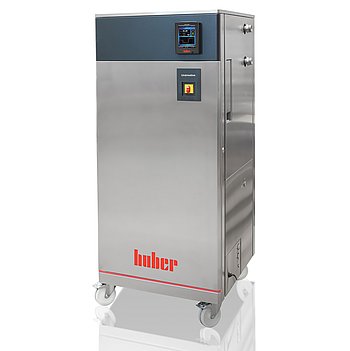
Peter Huber Kältemaschinenbau Unimotive GL 60w-XT
Peter Huber Kältemaschinenbau Unimotive GL 60w-XT — Temperature control units.
Water-cooled temperature control unit with magnetically coupled stainless-steel pump and 48 kW heating capacity, covering -45 to 150 °C using water-ethylene glycol mixtures. The GL 60w-XT is the high-capacity XT modification of the Unimotive series, distinguished by R-744 (GWP 1) first-stage refrigerant and a fixed-speed pump with M38x1.5 male connections. It serves automotive temperature simulation and material testing where precise, wide-range fluid conditioning is required.
Peter Huber Kältemaschinenbau Unimotive Series — Model Comparison & Selection
| Model | Display resolution | Heating capacity, W | Power supply | Pump connection | Refrigerant | Safety class |
|---|---|---|---|---|---|---|
| Unimotive GL 60w-XT Current | 0, 01 | 48000 | 400V 3~ 50Hz | M38x1, 5 AG male | R-744 (A1, H280) | I / NFL |
| Unimotive 10w | 0.01 | 12000 | 400V 3~ 50Hz | M38x1,5 AG male | R-452A (A1, H280) | III / FL |
| Unimotive 10w-XT | 0, 01 | 12000 | 400V 3~ 50Hz | M38x1, 5 AG male | R-452A (A1, H280) | I / NFL |
| Unimotive 20w | 0, 01 | 12000 | 400V 3~ 50Hz | M38x1, 5 AG male | R-452A (A1, H280) | III / FL |
| Unimotive 20w-XT | 0, 01 | 12000 | 400V 3~ 50Hz | M38x1, 5 AG male | R-452A (A1, H280) | I / NFL |
| Unimotive 26w | 0, 01 K | 24000 | 400V 3~ 50Hz | M38x1, 5 AG male | R-452A (A1, H280) | III / FL |
| Unimotive 26w-XT | 0, 01 | 24000 | 400V 3~ 50Hz | M38x1, 5 AG male | R-452A (A1, H280) | I / NFL |
| Unimotive 27w | 0, 01 | 24000 | 400V 3~ 50Hz | M38x1, 5 AG male | R-452A (A1, H280) | III / FL |
| Unimotive GL 07w | 0, 01 | 12000 | 400V 3~ 50Hz | M38x1, 5 AG male | R-744 (A1, H280) | III / FL |
| Unimotive GL 07w-XT | 0, 01 | 12000 | 400V 3~ 50Hz | M38x1, 5 AG male | R-744 (A1, H280) | I / NFL |
| Unimotive GL 10w | 0, 01 | 24000 | 460V 3~ 60Hz | M38x1, 5 AG male | R-744 (A1, H280) | III / FL |
| Unimotive GL 10w-XT | 0, 01 | 24000 | 460V 3~ 60Hz | M38x1, 5 AG male | R-744 (A1, H280) | I / NFL |
| Unimotive GL 20w | 0, 01 | 24000 | 400V 3~ 50Hz | M38x1, 5 AG male | R-744 (A1, H280) | III / FL |
| Unimotive GL 20w-XT | 0, 01 | 24000 | 400V 3~ 50Hz | M38x1, 5 AG male | R-744 (A1, H280) | I / NFL |
| Unimotive GL 30w | 0, 01 | 24000 | 460V 3~ 60Hz | M38x1, 5 AG male | R-744 (A1, H280) | III / FL |
| Unimotive GL 50w | 0, 01 | 24000 | 400V 3~ 50Hz | M38x1, 5 AG male | R-744 (A1, H280) | III / FL |
| Unimotive GL 50w-XT | 0, 01 | 24000 | 400V 3~ 50Hz | M38x1, 5 AG male | R-744 (A1, H280) | I / NFL |
| Unimotive GL 60w | 0, 01 | 48000 | 400V 3~ 50Hz | M38x1, 5 AG male | R-744 (A1, H280) | III / FL |
Full specifications
| Control output | POKO ONE (potential-free contact) |
| Heating capacity | 48 kW |
| Pump connection | M38x1, 5 AG male |
| Pump speed adjustable | no |
| Pump type | magnetically coupled, stainless steel |
| External sensor connection | Pt100 |
| Temperature range | -45...150 °C |
| Power supply | 400V 3~ 50Hz |
| Controller | Pilot ONE |
| Display resolution | 0, 01 K |
| Digital interface | Ethernet, USB (Host u. Device), RS232 |
| Refrigerant | R-744 (A1, H280) (1st stage) |
| Maximum viscosity | 200 mm²/s (max) |
| Ambient temperature limit | 5...40 °C (permissible) |
| Cooling water connection | G3/4 male |
| Cooling water differential pressure | 1 bar (min) |
| Cooling Water Pressure | 6 bar (max) |
| Protection rating | IP20 |
| Safety class | I / NFL |
Description
Construction and series positioning
The Unimotive GL 60w-XT is a water-cooled temperature control unit built for operation with water-ethylene glycol mixtures including corrosion protection down to -45 °C. Its refrigeration circuit uses natural refrigerant R-744 (A1, H280) in the first stage, giving a GWP of 1. The pump is magnetically coupled and made of stainless steel, with a fixed (non-adjustable) speed and M38x1.5 male pump connections. Within the Unimotive series, the GL 60w-XT is the high-capacity XT variant; sibling models 10w, 10w-XT, 20w and 20w-XT are smaller-capacity units. The XT designation and the 60 size code identify this modification, not a rating.
Working range and media behavior
- Temperature range: -45 to 150 °C.
- Heating capacity: 48 kW.
- Maximum permissible kinematic viscosity of the thermal fluid: 200 mm²/s, which limits fluid choice at low temperatures.
- Maximum system pressure: 12 bar; external circuit and expansion vessel must be rated accordingly.
- Cooling water: intake temperature 5 to 20 °C, minimum differential pressure 1 bar, maximum pressure 6 bar, connection G3/4 male. Cooling power is rated at 20 °C room temperature, 15 °C cooling water inlet and 1 bar differential pressure; actual capacity will differ if site conditions deviate.
- Cooling water circuit materials include copper, stainless steel 1.4401, MS, PA, PPE, PTFE and EPDM; only compatible cooling water may be used. Sea water is prohibited; only drinking water or filtered river/sea water is permitted.
Control, interfaces and operation
The unit uses the Pilot ONE controller with POKO ONE potential-free contact output. Display resolution is 0.01 K. Interfaces include Ethernet, USB (Host and Device) and RS232. An external Pt100 sensor connection is provided. The unit is rated IP20 and requires a 400 V 3~ 50 Hz supply. Voltage tolerance is ±5% only with simultaneous frequency tolerance of ±2%; combinations such as -5% voltage with +2% frequency are not allowed. Three-phase devices below 63 A are supplied with cable but without plug; above 63 A without cable and without plug. Ambient temperature must stay between 5 and 40 °C. The unit is a Group 1 Class A device per EN55011 for industrial EMC environments. It must not be installed or started inside an ATEX zone. A drip tray for condensate/heat transfer fluid must be installed below the unit by the responsible body. Cooling water supply should be shut off during downtimes because flow can occur even when the unit is switched off. A backflow preventer on the building side is required. Outdoor installation requires frost-protected cooling water lines and a minimum cooling water temperature of 5 °C. The unit must always be connected to a socket with protective earth; hardwiring must be done by a certified electrician. Replacement power cables are limited to 3 m for 1–2 phase and 4 m for 3-phase connections. Heat transfer fluid must be brought to room temperature before switching off to avoid overpressure. Hose inside diameters must at least match the pump connections, with larger diameters for longer lines. For pressure-sensitive applications such as glass reactors, the maximum flow pressure must be considered and an external bypass may be needed.
Integration & Operating Notes
Cooling water intake below 5 °C or above 20 °C, or differential pressure below 1 bar, will reduce cooling capacity or prevent specified operation. Maximum cooling water pressure is 6 bar. If cooling water temperature falls below the condensation point, internal cooling water pipes must be insulated to prevent condensation.
The unit requires 400 V 3~ 50 Hz. Voltage tolerance is ±5% with simultaneous frequency tolerance of ±2%; combinations such as -5% voltage with +2% frequency are not allowed. Three-phase devices below 63 A are supplied with cable but without plug; above 63 A without cable and without plug. Always connect to a socket with protective earth; hardwiring must be done by a certified electrician.
The responsible body must install a condensation water / heat transfer fluid drip tray below the unit. Minimum wall clearances depend on air- or water-cooling and on whether the unit runs with or without a bath. The unit must not be installed or started inside an ATEX zone. Refrigerant charge and room size must be checked to avoid dangerous refrigerant concentration.
Only drinking water or filtered river/sea water may be used as cooling water; sea water must not be used. The cooling water circuit contains copper, stainless steel 1.4401, MS, PA, PPE, PTFE and EPDM, so only compatible cooling water may be used. A backflow preventer on the building side is required. Shut off cooling water supply during downtimes because flow can occur even when the unit is switched off.
Maximum permissible kinematic viscosity of the thermal fluid is 200 mm²/s, limiting fluid choice at low temperatures. Maximum system pressure is 12 bar, so the external circuit and expansion vessel must be rated accordingly. Heat transfer fluid must be brought to room temperature before switching off to avoid overpressure.
When cooling water temperatures fall below the condensation point, it is essential to insulate the cooling water pipes in the unit to prevent condensation damage and electrical risk. Outdoor installation requires frost-protected cooling water lines and a minimum cooling water temperature of 5 °C.
Selection & Integration Q&A
Choose the GL 60w-XT when you need 48 kW heating capacity and the -45 to 150 °C range for larger thermal loads. The 10w/20w variants are smaller-capacity units; select them only if their lower capacity meets your load. The XT designation indicates this modification, not a rating.
Cooling water: 5–20 °C intake, 1 bar min differential pressure, 6 bar max, G3/4 male connection. Pump connections are M38x1.5 male with bore shape Y (60°) per DIN 3863; mating hoses need ball socket per DIN 3863 and sleeve nut per DIN 3870. Hose ID must at least match pump connections.
Ambient temperature 5–40 °C. Do not install in an ATEX zone. Install a drip tray below the unit. Respect wall clearances per manual. Outdoor installation requires frost-protected cooling water lines and min 5 °C cooling water. Unit is Group 1 Class A per EN55011 for industrial EMC environments.
Customer must provide a suitable plug for three-phase devices below 63 A (cable supplied) or full cabling above 63 A (no cable/plug). A backflow preventer on the building side is required. Insulate cooling water pipes if below condensation point. Shut off cooling water during downtimes. No consumables listed in base delivery.