
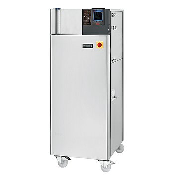
Peter Huber Kältemaschinenbau Unistat 912w Dynamisches
Peter Huber Kältemaschinenbau Unistat 912w Dynamisches — Temperature control units with Noise level 65 dB.
The Unistat 912w Dynamisches is a water-cooled, dynamically temperature-controlled unit with a -90 to 250 °C range and 6 kW heating capacity. It is distinguished within the Unistat series by its water cooling and dynamic control, requiring a 400 V three-phase supply and cooling water at 5–20 °C. It serves precise temperature control of externally closed or open circuits in industrial processes.
Peter Huber Kältemaschinenbau Unistat Series — Model Comparison & Selection
| Model | Noise level, dB | Ambient temperature limit, °C | Display resolution | Power supply | Pump connection | Pump type |
|---|---|---|---|---|---|---|
| Unistat 912w Dynamisches Current | 65 | 5–40 | 0, 01 | 400V 3~ 50Hz | M30x1, 5 AG male | magnetically coupled, st |
| Unistat 1005w Dynamisches | — | 5–40 | 0, 01 | 400V 3~ 50Hz | M30x1, 5 AG male | Pressure pump, variable |
| Unistat 1015w Dynamisches | — | 5–40 | 0, 01 | 400V 3~ 50Hz | M30x1, 5 AG male | magnetically coupled, st |
| Unistat 705w Dynamisches | — | 5–40 | 0, 01 | 230V 1~ 50Hz | M24x1, 5 AG male | Pressure pump, variable |
| Unistat 815w Dynamisches | 60 | 5–40 | 0, 01 | 400V 3~ 50Hz | M30x1, 5 AG male | Pressure pump, variable |
| Unistat 825w Dynamisches | — | 5–40 | 0, 01 | 400V 3~ 50Hz | M30x1, 5 AG male | Pressure pump, variable |
| Unistat 905w Dynamisches | — | 5–40 | 0, 01 K | 208V 3~ 60Hz | M30x1, 5 AG male | magnetically coupled, st |
| Unistat 915w Dynamisches | 64 | 5–40 | 0, 01 | 400V 3~ 50Hz | M30x1, 5 AG male | magnetically coupled, st |
| Unistat 920w Dynamisches | 71 | 5–40 | 0, 01 | 400V 3~ 50Hz | M38x1, 5 AG male | magnetically coupled, st |
| Unistat 930w Dynamisches | — | 5–40 | 0, 01 | 460V 3~ 60Hz | M38x1, 5 AG male | magnetically coupled, st |
| Unistat 950w Dynamisches | — | 5–40 | 0, 01 | 400V 3~ 50Hz | flange DN40 PN10/40 EN10 | magnetically coupled, st |
| Unistat P815 Dynamisches | 64 | 5–40 | 0, 01 | 400V 3~ 50Hz | M30x1, 5 AG male | magnetically coupled, st |
| Unistat P815w Dynamisches | — | 5–40 | 0, 01 | 400V 3~ 50Hz | M30x1, 5 AG male | magnetically coupled, st |
| Unistat P825 Dynamisches | — | 5–40 | 0, 01 | 400V 3~ 50Hz | M30x1, 5 AG male | magnetically coupled, st |
| Unistat P825w Dynamisches | — | 5–40 | 0, 01 | 400V 3~ 50Hz | M30x1, 5 AG male | magnetically coupled, st |
| Unistat P905 Dynamisches | — | 5–35 | 0, 01 | 460V 3~ 60Hz | M30x1, 5 AG male | magnetically coupled, st |
| Unistat P905w Dynamisches | — | 5–40 | 0, 01 | 460V 3~ 60Hz | M30x1, 5 AG male | magnetically coupled, st |
| Unistat P912w Dynamisches | 65 | 5–40 | 0, 01 | 460V 3~ 60Hz | M30x1, 5 AG male | magnetically coupled, st |
| Unistat P915w Dynamisches | 64 | 5–40 | 0, 01 | 400V 3~ 50Hz | M30x1, 5 AG male | magnetically coupled, st |
| Unistat P920w Dynamisches | — | 5–40 | 0, 01 | 400V 3~ 50Hz | M38x1, 5 AG male | magnetically coupled, st |
| Unistat P925w Dynamisches | — | 5–40 | 0, 01 | 400V 3~ 50Hz | M38x1, 5 AG male | magnetically coupled, st |
| Unistat P930w Dynamisches | — | 5–40 | 0, 01 | 400V 3~ 50Hz | M38x1, 5 AG male | magnetically coupled, st |
| Unistat P950w Dynamisches | — | 5–40 | 0, 01 | 400V 3~ 50Hz | flange DN40 PN10/40 EN10 | magnetically coupled, st |
Full specifications
| Noise level | 65 dB(A) |
| Control output | POKO ONE |
| Heating capacity | 6 kW |
| Pump connection | M30x1, 5 AG male |
| Pump speed adjustable | Yes |
| Pump type | magnetically coupled, stainless steel |
| External sensor connection | Pt100 |
| Temperature range | -90...250 °C |
| Weight | 328 kg |
| Current consumption | 20 A (max.) |
| Power supply | 400V 3~ 50Hz |
| Controller | Pilot ONE |
| Display resolution | 0, 01 K |
| Digital interface | Ethernet, USB (Host u. Device), RS232 |
| Maximum viscosity | 50 mm²/s |
| Ambient temperature limit | 5...40 °C |
| Cooling water connection | G1/2 male |
| Cooling water consumption | 516 l/h (at 15°C, flow 0°C) |
| Cooling water differential pressure | 1 bar (min.) |
| Cooling Water Pressure | 6 bar (max.) |
| Protection rating | IP20 |
| Safety class | III / FL |
Description
Construction and positioning
- The Unistat 912w Dynamisches is a water-cooled (w) model in the Unistat series, using a magnetically coupled stainless steel pump and Pilot ONE controller. It is a free-standing unit with a 328 kg mass and IP20 protection.
- Compared to sibling models such as the Unistat 815w (60 dB(A)) and air-cooled variants, this model is water-cooled, requiring a facility cooling water loop. The 'Dynamisches' designation indicates dynamic temperature control capability.
Behavior under load and media
- The temperature range is -90 to 250 °C, with a heating capacity of 6 kW. Cooling capacity depends on cooling water temperature; performance derates as water temperature rises above the 15 °C reference, and flow may need to increase.
- The maximum permissible kinematic viscosity of the heat transfer fluid is 50 mm²/s, limiting fluid selection at low temperatures. The unit has a minimum filling capacity of 3.9 l and an expansion tank capacity of 6.5 l.
- Safety classification III/FL with adjustable overtemperature protection per DIN 12876. Process Safety mode releases maximum cooling at the OT trigger instead of shutting down.
Installation, connection and control
- Requires a 400 V 3~ 50 Hz supply with max 20 A current and 3x20 A fusing; delivered with cable but without plug. Voltage tolerance ±5% only with frequency tolerance ±2%, and certain combinations are not allowed.
- Cooling water connection is G1/2 male, min differential pressure 1 bar, max pressure 6 bar, consumption 516 l/h at 15 °C. Pump connection is M30x1.5 male per DIN 3863, requiring ball socket DIN 3863 and sleeve nut DIN 3870.
- Controller Pilot ONE with Ethernet, USB (Host and Device), RS232 interfaces; external Pt100 sensor connection. Display resolution 0.01 K. Pump speed adjustable.
- Installation ambient 5–40 °C, IP20, sound pressure 65 dB(A) ±4 dB(A). Must not be installed in ATEX zones. EMC Class A, Group 1 to EN55011.
Integration & Operating Notes
The unit draws up to 20 A per phase and requires a 400 V three-phase supply with 3x20 A fusing. Voltage tolerance is ±5% only with simultaneous frequency tolerance of ±2%, and combinations such as -5% voltage with +2% frequency are not allowed. The electrical installation must be sized accordingly, and a suitable plug must be provided on site since the unit is delivered with cable but without plug.
The cooling water connection is G1/2 male and requires a minimum differential pressure of 1 bar and a maximum pressure of 6 bar. The unit is designed for cooling water intake between 5 °C and 20 °C; below the condensation point, cooling water pipes must be insulated. Cooling capacity drops as water temperature rises, and required flow may increase, so performance must be derated for warmer facility water.
The unit must not be installed or started up within an ATEX zone; explosion protection requires an Ex px cabinet. It must be installed at ambient temperatures between 5 °C and 40 °C in a dry, protected location due to IP20 protection. A condensation water/heat transfer fluid drip tray must be installed below the unit, and local regulations may prescribe it.
The maximum permissible kinematic viscosity of the heat transfer fluid is 50 mm²/s, so the selected fluid must remain below this limit across the entire operating temperature range. The unit has a minimum filling capacity of 3.9 l and an expansion tank filling capacity of 6.5 l, so the external circuit volume and fluid charge must be planned within these limits.
In Process Safety mode, when the set overtemperature trigger value is reached, the controller releases maximum cooling capacity instead of switching off all poles. This mode requires the compressor to be set to Permanently ON to keep cooling active at the OT trigger. The power failure behavior can be set to Off/Standby or ON/Temperature control active via Pilot ONE.
Shut off the cooling water supply even for shorter downtimes such as overnight to prevent water damage and unnecessary load. Hoses and connections must be periodically checked for leaks and quality and replaced as needed. Work on the coolant circuit must be carried out by approved refrigeration/air-conditioning contractors.
Selection & Integration Q&A
Choose the 912w when you need water cooling and a -90 to 250 °C range with 6 kW heating. The 815w is air-cooled (60 dB(A)) and may suit sites without cooling water. The 912w requires a facility cooling water loop at 5–20 °C and 1–6 bar differential pressure.
Cooling water: G1/2 male, min 1 bar differential, max 6 bar, 516 l/h at 15 °C. Pump: M30x1.5 male per DIN 3863; use ball socket DIN 3863 and sleeve nut DIN 3870. Ensure cooling water temperature 5–20 °C and insulate pipes below dew point.
Periodically check hoses and connections for leaks and quality; replace as needed. Shut off cooling water during downtimes. Clean liquefier fins and strainer. The unit is delivered with cable but without plug; mating fittings for pump and cooling water must be procured separately.