
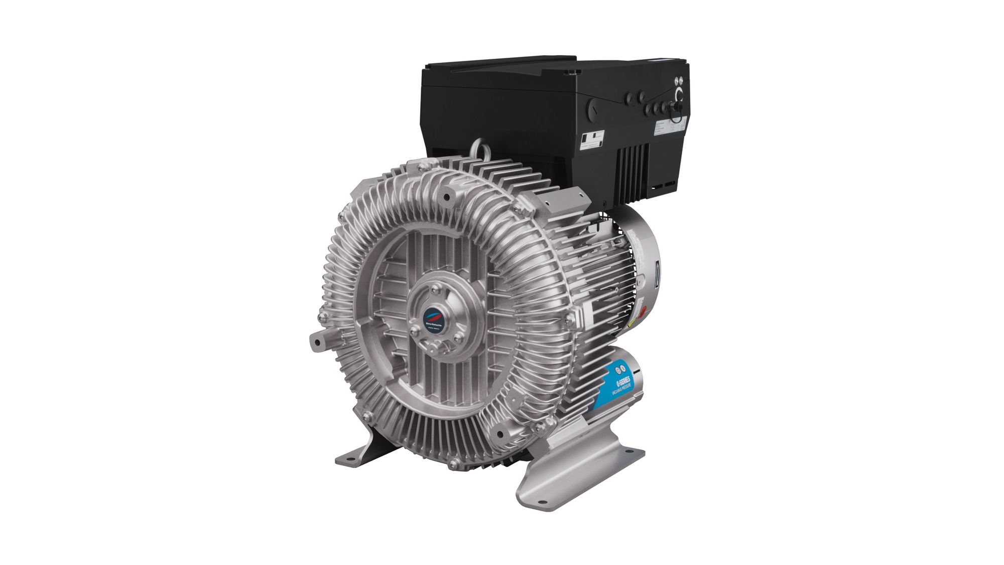
Elmo Rietschle 2BH1940
Elmo Rietschle 2BH1940 — Side-Channel / Regenerative Ring Blowers with Max. differential pressure -150 mbar, Motor power 17.3 kW, Noise level 77 dB.
The Elmo Rietschle 2BH1940 is a side-channel regenerative ring blower in the G-BH1 series, configured as a single-stage, contactless impeller unit. It is positioned above the 2BH10xx siblings for higher flow and pressure duties. It serves as a vacuum or pressure source in pneumatic conveying, aeration, and industrial process air systems.
Elmo Rietschle G-BH1 Series — Model Comparison & Selection
| Model | Motor power, kW | Noise level, dB | Weight, kg | Max. differential pressure, mbar | Current, A | Protection rating |
|---|---|---|---|---|---|---|
| 2BH1940 Current | 19.9 | 73 | 303 | -150 | 63.1 | IP55 |
| 2BH1009 | — | — | — | — | — | — |
| 2BH1014 | 0.32 | 57 | 11 | -55 | 3.2–6.5 | IP55 |
| 2BH1015 | 1.3 | 64 | 21 | -180 | 8–16 | IP55 |
| 2BH1023 | 1.75 | 69 | 69 | -190 | 10–20 | IP55 |
| 2BH1035 | 2.2 | 64 | 70 | -140 | 14.3–27 | IP55 |
| 2BH1100 | 0.2 | 53 | 10 | -120 | 1.39 Δ / 0.80 Y | IP 55 |
| 2BH1200 | 0.29 | 40 | 57 | -40 | 1.38 0.8 Y | IP55 |
| 2BH1300 | 0.29 | 100 | 51 | -100 | 1.9 | IP 55 |
| 2BH1310 | 0.7 | 56 | 16 | -250 | 3.8 Δ / 2.20 Y | IP55 |
| 2BH1330 | 0.29 | 80 | 51 | — | 1.74 Δ / 1.0 Y | IP55 |
| 2BH1400 | 0.95 | 61 | 16 | -180 | 5.6 | IP55 |
| 2BH1410 | 2 | 65 | 28 | -300 | 6.9 | IP55 |
| 2BH1430 | 1.1 | 64 | 16 | 110 | 4.2 | IP55 |
| 2BH1490 | 0.95 | 61 | 16 | -140 | 4.8 VV | IP55 |
| 2BH1500 | 0.95 | 65 | 21 | -90 | 4.2 | IP55 |
| 2BH1510 | 4 | 71 | 48 | -400 | 7.6–15.2 | IP55 |
| 2BH1530 | 1.6 | 69 | 25 | -90 | 4.7 | IP55 |
| 2BH1590 | 1.3 | 61 | 21 | -190 | 2.75 | IP55 |
| 2BH1600 | 1.75 | 72 | 31 | 130 | 9.9 | IP55 |
| 2BH1610 | 2.5 | 75 | 48 | 160 | 6 | IP55 |
| 2BH1630 | 2.5 | 64 | 36 | -160 | 17.1 | IP55 |
| 2BH1640 | 4.6 | 65 | 65 | -240–260 | 17.1 | IP55 |
| 2BH1690 | 2.5 | 64 | 34 | -200 | 9.9 | IP55 |
| 2BH1800 | 5.8 | 77 | 131 | 260 | 11–22 | IP55 |
| 2BH1810 | 9.9 | 74 | 188 | -460 | 30.8 | IP55 |
| 2BH1830 | 5.8 | 75 | 133 | -160 | 19.4 | IP55 |
| 2BH1900 | 8.6 | 71 | 183 | -190 | 30.8 | IP55 |
| 2BH1910 | 12.6 | 76 | 295 | -220 | 26.4 | IP55 |
| 2BH1930 | 8.6 | 75 | 212 | -80 | 17.6–35.2 | IP55 |
| 2BH1943 | 17.3 | 77 | 330 | -160 | 72.2 UU / 36.1 U | IP55 |
Full specifications
| Max. differential pressure | -150 mbar (50 Hz) 60 Hz: -110 mbar |
| Motor power | 17.3 kW (50 Hz) 60 Hz: 19.9 kW |
| Noise level | 73 dB (50 Hz) 60 Hz: 77 dB |
| Weight | 303 kg (50 Hz) 60 Hz: 303 kg |
| Number of stages | 1 |
| Current | 63.1 A (50 Hz) 60 Hz: 72.2 / 36.1 A |
| Frequency | 50 Hz (50 Hz) 60 Hz: 60 Hz |
| Voltage | 190-210 V (50 Hz) 60 Hz: 190-210 / 380-480 V |
| Protection rating | IP55 |
| Operating temperature | 25 degC |
Description
Construction and Series Positioning
- The 2BH1940 is a side-channel (regenerative) blower: a rotating impeller transfers kinetic energy to the gas through repeated radial recirculation in the ring channel, producing pressure or vacuum without internal contact or sealing fluid.
- Within the G-BH1 series, the 2BH1940 is positioned above the sibling models 2BH1009, 2BH1014, 2BH1015, and 2BH1023, which are smaller frames covering lower flow and pressure ranges. Select the 2BH1940 when the duty point requires higher flow/pressure capability; select a smaller sibling when the duty point falls within its narrower range to avoid oversizing.
- No performance curves, electrical data, or dimensional specifications were supplied for this model; the statements below are limited to the series architecture and general side-channel blower behavior.
Behavior Under Load and in Different Media
- Because the impeller does not contact the casing, the machine is oil-free in the conveying chamber and can handle air and neutral gases. Pressure and vacuum rise along the characteristic curve as flow decreases; the exact curve for the 2BH1940 was not provided and must be obtained from the manufacturer before sizing.
- Operation at or near closed suction/discharge (zero flow) produces the maximum temperature rise and should be limited by the process design; continuous operation at the end of the curve requires thermal verification.
Installation, Connection, and Control
- No installation manual, wiring diagram, or control documentation was attached for this model. Mounting orientation, flange sizes, electrical connection details, and control interfaces must be taken from the official Elmo Rietschle documentation for the 2BH1940 before integration.
- The machine is a direct-driven unit; the motor and blower share a shaft, so no belt or coupling alignment is required, but the mounting base must be flat and rigid to avoid casing distortion.
Integration & Operating Notes
Side-channel blowers reach their highest discharge temperature at closed-valve (zero flow) operation. The 2BH1940 must not be run continuously against a closed suction or discharge unless the manufacturer confirms the permissible temperature rise for this frame; install a relief valve or bypass if the process can dead-head.
The blower casing and motor are a single rigid assembly; bolting to an uneven surface can distort the close impeller-to-casing clearance. Use a machined base or shims and tighten fasteners evenly. Exact bolt pattern and weight were not provided and must be taken from the 2BH1940 dimensional drawing.
No electrical specifications were supplied for the 2BH1940. Voltage, frequency, current, and starting method must be read from the motor nameplate and the official datasheet. Direct-on-line starting of a large frame draws high inrush current; verify the supply and protection coordination before commissioning.
Selection & Integration Q&A
Pick the 2BH1940 only when the required flow/pressure point exceeds the range of the 2BH1023 and the other smaller frames. If the duty point fits a smaller sibling, choose it to avoid oversizing, higher energy use, and unstable operation near the blower's flow limit.
Confirm the motor nameplate voltage/frequency/current against the supply, size the starter or VFD for the frame's inrush, and match suction/discharge flange sizes to the 2BH1940 drawing. Add a suction filter and, if the process can dead-head, a relief valve or bypass.
Mount on a flat rigid base to preserve impeller clearance, and keep the cooling-air path to the motor unobstructed. Continuous operation at closed suction or discharge raises temperature; verify permissible thermal limits with the manufacturer before specifying a dead-head duty cycle.
The base unit does not include suction filters, relief valves, silencers, flexible connectors, or mounting pads; these must be ordered separately. Bearing inspection intervals and any replacement parts must be taken from the official 2BH1940 manual, which was not supplied with this record.