
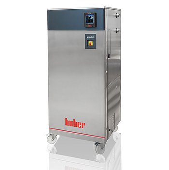
Peter Huber Kältemaschinenbau Unistat GL P535w Dynamisches
Peter Huber Kältemaschinenbau Unistat GL P535w Dynamisches — Temperature control units.
The Unistat GL P535w Dynamisches is a water-cooled, CO2 (R-744) refrigerant, high-pressure-drop free-standing temperature control unit rated -50 to 200 °C with 12 kW heating and a magnetically coupled stainless-steel pump. It is the GL/P/w modification of the Unistat 5xx series, distinguished by CO2 refrigerant, high-pressure-drop process suitability and water cooling. It serves precise temperature control of externally closed or open applications via the Pilot ONE controller.
Peter Huber Kältemaschinenbau Unistat Series — Model Comparison & Selection
| Model | Noise level, dB | Display resolution | Heating capacity, W | Pump connection | Pump type | Temperature range, °C |
|---|---|---|---|---|---|---|
| Unistat GL P535w Dynamisches Current | — | 0, 01 | 12000 | M38x1, 5 AG male | magnetically coupled, st | -50–200 |
| Unistat 510w Dynamisches | 60 | 0, 01 | 6000 | M30x1, 5 AG male | magnetically coupled, st | -50–250 |
| Unistat 515w Dynamisches | — | 0, 01 | 6000 | M30x1, 5 AG male | magnetically coupled, st | -50–250 |
| Unistat 520w Dynamisches | 61 | 0, 01 | 6000 | M30x1, 5 AG male | magnetically coupled, st | -55–250 |
| Unistat 525 Dynamisches | 56 | 0, 01 | 6000 | M30x1, 5 AG male | magnetically coupled, st | -55–250 |
| Unistat 525w Dynamisches | 61 | 0, 01 | 6000 | M30x1, 5 AG male | magnetically coupled, st | -55–250 |
| Unistat 527w Dynamisches | — | 0, 01 | 12000 | M38x1, 5 AG male | magnetically coupled, st | -55–250 |
| Unistat 530w Dynamisches | 59 | 0, 01 | 12000 | M38x1, 5 AG male | magnetically coupled, st | -55–250 |
| Unistat 540w Dynamisches | — | 0, 01 | 24000 | M38x1, 5 AG male | magnetically coupled, st | -55–250 |
| Unistat 545w Dynamisches | — | 0, 01 | 24000 | M38x1, 5 AG male | magnetically coupled, st | -55–250 |
| Unistat 610w Dynamisches | 62 | 0, 01 | 6000 | M30x1, 5 AG male | magnetically coupled, st | -60–200 |
| Unistat 615w Dynamisches | 62 | 0, 01 | 12000 | M30x1, 5 AG male | Pressure pump, variable | -60–200 |
| Unistat 620w Dynamisches | 68 | 0, 01 | 12000 | M38x1, 5 AG male | magnetically coupled, st | -60–200 |
| Unistat 625w Dynamisches | — | 0, 01 | 12000 | M38x1, 5 AG male | magnetically coupled, st | -60–200 |
| Unistat 630w Dynamisches | — | 0, 01 | 24000 | M38x1, 5 AG male | magnetically coupled, st | -60–200 |
| Unistat 635w Dynamisches | — | 0, 01 | 24000 | M38x1, 5 AG male | magnetically coupled, st | -60–200 |
| Unistat 640w Dynamisches | — | 0, 01 | 24000 | M38x1, 5 AG male | magnetically coupled, st | -60–200 |
| Unistat 645w Dynamisches | — | 0, 01 | 36000 | flange DN32 PN10/40 EN10 | magnetically coupled, st | -60–200 |
| Unistat 650w Dynamisches | 73 | 0, 01 | 48000 | flange DN32 PN10/40 EN10 | magnetically coupled, st | -60–200 |
| Unistat 680w Dynamisches | — | 0, 01 | 96000 | DN50 PN16 (DIN EN 1092-1 | magnetically coupled, st | -60–200 |
| Unistat GL 530w Dynamisches | 61 | 0, 01 | 6000 | M38x1, 5 AG male | magnetically coupled, st | -50–200 |
| Unistat GL 535w Dynamisches | — | 0, 01 | 12000 | M38x1, 5 AG male | magnetically coupled, st | -50–200 |
| Unistat GL 540w Dynamisches | — | 0, 01 | 12000 | M38x1, 5 AG male | magnetically coupled, st | -50–200 |
| Unistat GL 550w Dynamisches | — | 0, 01 | 24000 | M38x1, 5 AG male | magnetically coupled, st | -50–200 |
| Unistat GL 560w Dynamisches | — | 0, 01 | 24000 | M38x1, 5 AG male | magnetically coupled, st | -50–200 |
| Unistat GL 570w Dynamisches | — | 0, 01 | 48000 | M38x1, 5 AG male | magnetically coupled, st | -50–200 |
| Unistat GL P530w Dynamisches | 61 | 0, 01 | 6000 | M38x1, 5 AG male | magnetically coupled, st | -50–200 |
| Unistat GL P540w Dynamisches | — | 0, 01 | 12000 | M38x1, 5 AG male | magnetically coupled, st | -50–200 |
| Unistat GL P550w Dynamisches | — | 0, 01 | 24000 | M38x1, 5 AG male | magnetically coupled, st | -50–200 |
| Unistat GL P560w Dynamisches | — | 0, 01 | 24000 | M38x1, 5 AG male | magnetically coupled, st | -50–200 |
| Unistat GL P570w Dynamisches | — | 0, 01 | 48000 | M38x1, 5 AG male | magnetically coupled, st | -50–200 |
| Unistat P510 Dynamisches | 60 | 0, 01 | 6000 | M30x1, 5 AG male | magnetically coupled, st | -50–250 |
| Unistat P510w Dynamisches | 60 | 0, 01 | 6000 | M30x1, 5 AG male | magnetically coupled, st | -50–250 |
| Unistat P515w Dynamisches | — | 0, 01 | 6000 | M30x1, 5 AG male | magnetically coupled, st | -50–250 |
| Unistat P520 Dynamisches | — | 0, 01 | 6000 | M30x1, 5 AG male | magnetically coupled, st | -55–250 |
| Unistat P520w Dynamisches | 61 | 0, 01 | 6000 | M30x1, 5 AG male | magnetically coupled, st | -55–250 |
| Unistat P525 Dynamisches | 56 | 0, 01 | 6000 | M30x1, 5 AG male | magnetically coupled, st | -55–250 |
| Unistat P525w Dynamisches | 61 | 0, 01 | 6000 | M30x1, 5 AG male | magnetically coupled, st | -55–250 |
| Unistat P527w Dynamisches | 57 | 0, 01 | 12000 | M38x1, 5 AG male | magnetically coupled, st | -55–250 |
| Unistat P530w Dynamisches | 62 | 0.01 | 12000 | M38x1,5 AG male | magnetically coupled, st | -55–250 |
| Unistat P540w Dynamisches | — | 0, 01 | 24000 | M38x1, 5 AG male | magnetically coupled, st | -55–250 |
| Unistat P545w Dynamisches | — | 0, 01 | 24000 | M38x1, 5 AG male | magnetically coupled, st | -55–250 |
| Unistat P610 Dynamisches | — | 0, 01 | 6000 | M30x1, 5 AG male | magnetically coupled, st | -60–200 |
| Unistat P610w Dynamisches | 62 | 0, 01 | 6000 | M30x1, 5 AG male | magnetically coupled, st | -60–200 |
| Unistat P615 Dynamisches | — | 0, 01 | 12000 | M30x1, 5 AG male | magnetically coupled, st | -60–200 |
| Unistat P615w Dynamisches | 62 | 0, 01 | 12000 | M30x1, 5 AG male | magnetically coupled, st | -60–200 |
| Unistat P620w Dynamisches | — | 0, 01 | 12000 | M38x1, 5 AG male | magnetically coupled, st | -60–200 |
| Unistat P625w Dynamisches | — | 0, 01 | 12000 | M38x1, 5 AG male | magnetically coupled, st | -60–200 |
| Unistat P630w Dynamisches | — | 0, 01 | 24000 | M38x1, 5 AG male | magnetically coupled, st | -60–200 |
| Unistat P635w Dynamisches | — | 0, 01 | 24000 | M38x1, 5 AG male | magnetically coupled, st | -60–200 |
| Unistat P645w Dynamisches | — | 0, 01 | 36000 | flange DN32 PN10/40 EN10 | magnetically coupled, st | -60–200 |
| Unistat P650w Dynamisches | — | 0, 01 | 48000 | flange DN32 PN10/40 EN10 | magnetically coupled, st | -60–200 |
Full specifications
| Control output | POKO ONE |
| Heating capacity | 12 kW |
| Pump connection | M38x1, 5 AG male |
| Pump speed adjustable | Yes |
| Pump type | magnetically coupled, stainless steel |
| External sensor connection | Pt100 |
| Temperature range | -50...200 °C |
| Weight | 600 kg |
| Power supply | 400V 3~ 50Hz |
| Controller | Pilot ONE |
| Display resolution | 0, 01 K |
| Digital interface | Ethernet, USB (Host u. Device), RS232 |
| Maximum viscosity | 100 mm²/s |
| Ambient temperature limit | 5...40 °C |
| Cooling water connection | G3/4 male |
| Cooling water consumption | 2100 l/h (at 15°C, flow 0°C) |
| Cooling water differential pressure | 1 bar |
| Cooling Water Pressure | 6 bar |
| Protection rating | IP20 |
| Safety class | III / FL |
Description
Construction and series positioning
- Free-standing Unistat 5xx platform, 600 kg, 730×804×1738 mm, IP20, ambient 5–40 °C.
- Model-name decoding: GL = CO2 (R-744) refrigerant; P = for applications with high pressure drop; w = water cooled. Siblings 510w/515w/520w/525 Dynamisches are air-cooled or non-P variants of the same series.
- Refrigerant R-744 (A1, H280), GWP 1, 3.3 kg charge; cooling-water circuit materials include copper, 1.4401 stainless steel, MS, PA, PPE, PTFE, EPDM.
- Pump: magnetically coupled, stainless steel, speed-adjustable; pump connection M38×1.5 male (bore shape Y, 60°, DIN 3863).
Working range and behavior
- Temperature range -50…200 °C; heating capacity 12 kW; display resolution 0.01 K.
- Cooling capacity is rated at 20 °C room temperature, 15 °C cooling-water inlet and 1 bar differential pressure; higher cooling-water temperature reduces cooling power and may raise required flow.
- Cooling water: inlet 5–20 °C, differential pressure 1–4 bar, max pressure 6 bar, consumption 2100 l/h at 15 °C / flow 0 °C; connection G3/4 male.
- Max permissible kinematic viscosity of heat transfer fluid 100 mm²/s; safety class III/FL (DIN 12876), so FL fluids need fire point ≥65 °C and ethanol only under supervision.
Control, installation and operation
- Pilot ONE controller with POKO ONE control output; interfaces Ethernet, USB host and device, RS232; external Pt100 sensor connection.
- Power supply 400 V 3~ 50 Hz; three-phase devices below 63 A are delivered with cable but without plug; voltage tolerance ±5% and frequency ±2%, not combined in opposite directions.
- EMC class A group 1 (EN 55011); not for ATEX zones, medical devices or direct foodstuff temperature control.
- Externally closed applications: expansion vessel unlocked; externally open (bath) applications: expansion vessel locked. Process Safety mode requires compressor set to Permanently ON.
- Power Failure Auto can resume temperature control automatically after outage; alternative Off/Standby default requires manual start.
Integration & Operating Notes
The unit must not be installed or started within an ATEX zone; explosion protection requires a separate Ex px cabinet. The responsible body must install a condensation-water/heat-transfer-fluid drip tray below the unit, and local legislation may prescribe it. Plan floor loading for 600 kg and access routes for 730×804×1738 mm.
The unit requires 400 V 3~ 50 Hz. Three-phase devices with current consumption below 63 A are supplied with cable but without a plug, so the installer must provide a suitable connection. Voltage tolerance ±5% and frequency tolerance ±2% must not be combined in opposite directions. Hard-wired connection must be carried out by an electrician.
Cooling water inlet must be 5–20 °C with 1–4 bar differential pressure and no more than 6 bar pressure; consumption is 2100 l/h at 15 °C and flow 0 °C. Higher cooling-water temperature reduces cooling power and may require higher flow. If cooling water can fall below the dew point, insulate the internal cooling-water pipes. Shut off cooling water even for short downtimes such as overnight.
For externally closed applications the expansion vessel must remain unlocked; locking it causes overpressure damage. For externally open (bath) applications the expansion vessel must be locked to prevent fluid loss. Heat transfer fluid viscosity must not exceed 100 mm²/s; FL-rated fluids require fire point ≥65 °C and ethanol only under supervision.
In Process Safety mode the controller releases maximum cooling capacity at the overtemperature trigger instead of switching off all poles; this mode requires the compressor to be set to Permanently ON. Choose power-interruption behavior via Pilot ONE: Off/Standby (manual restart) or ON/Temperature control active (automatic restart, with a few-second INFO window to disable).
Check periodically for leaks and quality of hoses and hose connections and replace as required. Maintenance scope includes cleaning liquefier fins, cleaning the hat-type strainer/dirt trap (with draining the cooling circuit and dismantling the cooling water supply), emptying the drip tray, function test of the emergency stop switch, and heat transfer fluid inspection/replacement with circuit rinsing. Work on the coolant circuit must be done by approved refrigeration/air-conditioning contractors.
Selection & Integration Q&A
Choose the GL P535w when the process has high pressure drop (P), requires CO2 refrigerant (GL) and water cooling (w). The 510w/515w/520w are water-cooled without the P/GL designation; the 525 Dynamisches is a different modification. Confirm the process pressure drop and refrigerant preference before selecting.
Provide cooling water at 5–20 °C inlet, 1–4 bar differential pressure, max 6 bar, with G3/4 male connection; consumption is 2100 l/h at 15 °C and flow 0 °C. The circuit contains copper, 1.4401 stainless steel, MS, PA, PPE, PTFE and EPDM, so only compatible water may be used. Insulate internal pipes if water can fall below dew point.
Ambient must stay 5–40 °C; IP20; EMC class A group 1. Do not install in an ATEX zone. Transport and store upright only; allow about 2 hours acclimation when moving between cold and warm environments before power-on. Leveling feet must be activated and parking brakes engaged before commissioning.
Periodically check hoses and connections for leaks and quality and replace as needed; clean liquefier fins and the hat-type strainer/dirt trap; inspect/replace heat transfer fluid and rinse the circuit; test the emergency stop switch. The three-phase cable is supplied without a plug; pump fittings (M38×1.5 male, DIN 3863 ball socket and sleeve nut) and a drip tray are not included and must be provided.