
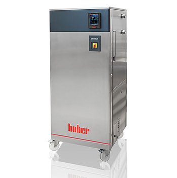
Peter Huber Kältemaschinenbau Unistat GL 535w Dynamisches
Peter Huber Kältemaschinenbau Unistat GL 535w Dynamisches — Temperature control units.
The Unistat GL 535w Dynamisches is a water-cooled, CO2 (R-744) refrigerant temperature control unit with a magnetically coupled stainless-steel pump and Pilot ONE controller, covering -50 to 200 °C. Within the Unistat 5xx series it is the GL (CO2) water-cooled modification, distinguished from air-cooled and high-pressure-drop siblings. It serves closed or open external circuits requiring 12 kW heating and up to 196 l/min circulation.
Peter Huber Kältemaschinenbau Unistat Series — Model Comparison & Selection
| Model | Noise level, dB | Display resolution | Heating capacity, W | Pump connection | Pump type | Temperature range, °C |
|---|---|---|---|---|---|---|
| Unistat GL 535w Dynamisches Current | — | 0, 01 | 12000 | M38x1, 5 AG male | magnetically coupled, st | -50–200 |
| Unistat 510w Dynamisches | 60 | 0, 01 | 6000 | M30x1, 5 AG male | magnetically coupled, st | -50–250 |
| Unistat 515w Dynamisches | — | 0, 01 | 6000 | M30x1, 5 AG male | magnetically coupled, st | -50–250 |
| Unistat 520w Dynamisches | 61 | 0, 01 | 6000 | M30x1, 5 AG male | magnetically coupled, st | -55–250 |
| Unistat 525 Dynamisches | 56 | 0, 01 | 6000 | M30x1, 5 AG male | magnetically coupled, st | -55–250 |
| Unistat 525w Dynamisches | 61 | 0, 01 | 6000 | M30x1, 5 AG male | magnetically coupled, st | -55–250 |
| Unistat 527w Dynamisches | — | 0, 01 | 12000 | M38x1, 5 AG male | magnetically coupled, st | -55–250 |
| Unistat 530w Dynamisches | 59 | 0, 01 | 12000 | M38x1, 5 AG male | magnetically coupled, st | -55–250 |
| Unistat 540w Dynamisches | — | 0, 01 | 24000 | M38x1, 5 AG male | magnetically coupled, st | -55–250 |
| Unistat 545w Dynamisches | — | 0, 01 | 24000 | M38x1, 5 AG male | magnetically coupled, st | -55–250 |
| Unistat 610w Dynamisches | 62 | 0, 01 | 6000 | M30x1, 5 AG male | magnetically coupled, st | -60–200 |
| Unistat 615w Dynamisches | 62 | 0, 01 | 12000 | M30x1, 5 AG male | Pressure pump, variable | -60–200 |
| Unistat 620w Dynamisches | 68 | 0, 01 | 12000 | M38x1, 5 AG male | magnetically coupled, st | -60–200 |
| Unistat 625w Dynamisches | — | 0, 01 | 12000 | M38x1, 5 AG male | magnetically coupled, st | -60–200 |
| Unistat 630w Dynamisches | — | 0, 01 | 24000 | M38x1, 5 AG male | magnetically coupled, st | -60–200 |
| Unistat 635w Dynamisches | — | 0, 01 | 24000 | M38x1, 5 AG male | magnetically coupled, st | -60–200 |
| Unistat 640w Dynamisches | — | 0, 01 | 24000 | M38x1, 5 AG male | magnetically coupled, st | -60–200 |
| Unistat 645w Dynamisches | — | 0, 01 | 36000 | flange DN32 PN10/40 EN10 | magnetically coupled, st | -60–200 |
| Unistat 650w Dynamisches | 73 | 0, 01 | 48000 | flange DN32 PN10/40 EN10 | magnetically coupled, st | -60–200 |
| Unistat 680w Dynamisches | — | 0, 01 | 96000 | DN50 PN16 (DIN EN 1092-1 | magnetically coupled, st | -60–200 |
| Unistat GL 530w Dynamisches | 61 | 0, 01 | 6000 | M38x1, 5 AG male | magnetically coupled, st | -50–200 |
| Unistat GL 540w Dynamisches | — | 0, 01 | 12000 | M38x1, 5 AG male | magnetically coupled, st | -50–200 |
| Unistat GL 550w Dynamisches | — | 0, 01 | 24000 | M38x1, 5 AG male | magnetically coupled, st | -50–200 |
| Unistat GL 560w Dynamisches | — | 0, 01 | 24000 | M38x1, 5 AG male | magnetically coupled, st | -50–200 |
| Unistat GL 570w Dynamisches | — | 0, 01 | 48000 | M38x1, 5 AG male | magnetically coupled, st | -50–200 |
| Unistat GL P530w Dynamisches | 61 | 0, 01 | 6000 | M38x1, 5 AG male | magnetically coupled, st | -50–200 |
| Unistat GL P535w Dynamisches | — | 0, 01 | 12000 | M38x1, 5 AG male | magnetically coupled, st | -50–200 |
| Unistat GL P540w Dynamisches | — | 0, 01 | 12000 | M38x1, 5 AG male | magnetically coupled, st | -50–200 |
| Unistat GL P550w Dynamisches | — | 0, 01 | 24000 | M38x1, 5 AG male | magnetically coupled, st | -50–200 |
| Unistat GL P560w Dynamisches | — | 0, 01 | 24000 | M38x1, 5 AG male | magnetically coupled, st | -50–200 |
| Unistat GL P570w Dynamisches | — | 0, 01 | 48000 | M38x1, 5 AG male | magnetically coupled, st | -50–200 |
| Unistat P510 Dynamisches | 60 | 0, 01 | 6000 | M30x1, 5 AG male | magnetically coupled, st | -50–250 |
| Unistat P510w Dynamisches | 60 | 0, 01 | 6000 | M30x1, 5 AG male | magnetically coupled, st | -50–250 |
| Unistat P515w Dynamisches | — | 0, 01 | 6000 | M30x1, 5 AG male | magnetically coupled, st | -50–250 |
| Unistat P520 Dynamisches | — | 0, 01 | 6000 | M30x1, 5 AG male | magnetically coupled, st | -55–250 |
| Unistat P520w Dynamisches | 61 | 0, 01 | 6000 | M30x1, 5 AG male | magnetically coupled, st | -55–250 |
| Unistat P525 Dynamisches | 56 | 0, 01 | 6000 | M30x1, 5 AG male | magnetically coupled, st | -55–250 |
| Unistat P525w Dynamisches | 61 | 0, 01 | 6000 | M30x1, 5 AG male | magnetically coupled, st | -55–250 |
| Unistat P527w Dynamisches | 57 | 0, 01 | 12000 | M38x1, 5 AG male | magnetically coupled, st | -55–250 |
| Unistat P530w Dynamisches | 62 | 0.01 | 12000 | M38x1,5 AG male | magnetically coupled, st | -55–250 |
| Unistat P540w Dynamisches | — | 0, 01 | 24000 | M38x1, 5 AG male | magnetically coupled, st | -55–250 |
| Unistat P545w Dynamisches | — | 0, 01 | 24000 | M38x1, 5 AG male | magnetically coupled, st | -55–250 |
| Unistat P610 Dynamisches | — | 0, 01 | 6000 | M30x1, 5 AG male | magnetically coupled, st | -60–200 |
| Unistat P610w Dynamisches | 62 | 0, 01 | 6000 | M30x1, 5 AG male | magnetically coupled, st | -60–200 |
| Unistat P615 Dynamisches | — | 0, 01 | 12000 | M30x1, 5 AG male | magnetically coupled, st | -60–200 |
| Unistat P615w Dynamisches | 62 | 0, 01 | 12000 | M30x1, 5 AG male | magnetically coupled, st | -60–200 |
| Unistat P620w Dynamisches | — | 0, 01 | 12000 | M38x1, 5 AG male | magnetically coupled, st | -60–200 |
| Unistat P625w Dynamisches | — | 0, 01 | 12000 | M38x1, 5 AG male | magnetically coupled, st | -60–200 |
| Unistat P630w Dynamisches | — | 0, 01 | 24000 | M38x1, 5 AG male | magnetically coupled, st | -60–200 |
| Unistat P635w Dynamisches | — | 0, 01 | 24000 | M38x1, 5 AG male | magnetically coupled, st | -60–200 |
| Unistat P645w Dynamisches | — | 0, 01 | 36000 | flange DN32 PN10/40 EN10 | magnetically coupled, st | -60–200 |
| Unistat P650w Dynamisches | — | 0, 01 | 48000 | flange DN32 PN10/40 EN10 | magnetically coupled, st | -60–200 |
Full specifications
| Control output | POKO ONE |
| Heating capacity | 12 kW |
| Pump connection | M38x1, 5 AG male |
| Pump speed adjustable | Yes |
| Pump type | magnetically coupled, stainless steel |
| External sensor connection | Pt100 |
| Temperature range | -50...200 °C |
| Weight | 531 kg |
| Power supply | 400V 3~ 50Hz |
| Controller | Pilot ONE |
| Display resolution | 0, 01 K |
| Digital interface | Ethernet, USB (Host u. Device), RS232 |
| Maximum viscosity | 100 mm²/s |
| Ambient temperature limit | 5...40 °C |
| Cooling water connection | G3/4 male |
| Cooling water consumption | 2100 l/h (at 15°C, flow 0°C) |
| Cooling water differential pressure | 1 bar |
| Cooling Water Pressure | 6 bar |
| Protection rating | IP20 |
| Safety class | III / FL |
Description
Construction and series positioning
- Water-cooled condenser (w suffix) with R-744 refrigerant (GWP 1, 3.5 kg charge); GL designates CO2 refrigerant rather than the standard HFC charge.
- Free-standing 5xx platform: 730×804×1738 mm, 531 kg net; leveling feet and casters (casters not for transport).
- Magnetically coupled stainless-steel pump, speed-adjustable, with M38×1.5 male pump connection (Y-bore per DIN 3863).
- Safety class III / FL per DIN 12876; IP20 enclosure; Pilot ONE controller with POKO ONE control output.
- Sibling models in the series (510w, 515w, 520w, 525) differ in cooling capacity and noise; the GL 535w is the CO2-refrigerant water-cooled variant.
Behavior under load and media
- Temperature range -50…200 °C; heating capacity 12 kW; display resolution 0.01 K.
- Pump curve: 196 l/min at zero head, 86 l/min at 2.0 bar, max delivery pressure 2.5 bar — external circuit pressure drop must be checked against this curve.
- Cooling water required at 5–20 °C inlet, 1–4 bar differential, max 6 bar; consumption 2100 l/h at 15 °C water and 0 °C flow.
- Published cooling capacity is valid only at 20 °C room, 15 °C cooling water and 1 bar differential; correct for site conditions.
- Cooling water circuit materials include copper, 1.4401 stainless, MS, PA, PPE, PTFE, EPDM — only compatible water may be used.
- Process Safety mode releases maximum cooling at the OT trigger instead of switching off; requires compressor set to Permanently ON.
Installation, control and operation
- 400 V 3~ 50 Hz supply; voltage tolerance ±5 %, frequency ±2 %, but −5 % voltage with +2 % frequency is not allowed.
- Three-phase units under 63 A are delivered with cable but without plug; hard-wiring by an electrician.
- Interfaces: Ethernet, USB host and device, RS232; external Pt100 sensor connection.
- Expansion vessel must remain unlocked for externally closed applications and locked for externally open (bath) applications.
- Allow ~2 h acclimation after cold/warm move before power-on; transport upright and emptied only.
- Shut off cooling water even for overnight downtime; periodically inspect hoses and connections.
Integration & Operating Notes
The unit accepts ±5 % voltage and ±2 % frequency, but a −5 % voltage combined with +2 % frequency is explicitly not allowed. Measure the actual site supply under load; a marginal feed can void the compressor warranty and cause start-up trips.
Inlet water below 5 °C or above 20 °C reduces capacity or causes condensation; differential pressure below 1 bar starves the condenser and above 4 bar risks damage. Install a pressure regulator and insulate pipes if water can fall below dew point.
The pump delivers 196 l/min at zero head but only 86 l/min at 2.0 bar, with a maximum of 2.5 bar. An external loop with high pressure drop will reduce flow below the required rate; calculate the circuit Δp at design flow before selecting this model over a P-variant.
Horizontal transport damages the compressor and a filled unit risks fluid overflow. After moving between cold and warm environments, allow about 2 hours acclimation before switching on to prevent condensation-induced electrical faults.
For externally closed applications the expansion vessel must remain unlocked; locking it causes overpressure damage. For externally open (bath) applications it must be locked to prevent fluid loss. Confirm this before commissioning.
The manual requires shutting off the cooling water supply even for short downtimes such as overnight to prevent water damage and unnecessary load on the circuit. Also periodically check hoses and connections for leaks and quality and replace as needed.
The unit must not be installed or started within an ATEX zone without an Ex px cabinet. Use with medical devices (e.g. in vitro diagnostic) or for direct foodstuff temperature control is not permissible. Plan site selection accordingly.
Selection & Integration Q&A
Choose the GL 535w when a water-cooled condenser and CO2 (R-744) refrigerant are required, e.g. for low-GWP compliance or when ambient air cooling is insufficient. Air-cooled or HFC-charged siblings suit sites without cooling water or where CO2 is not mandated.
Provide a 400 V 3~ 50 Hz feed with a suitable isolator (cable delivered without plug under 63 A) and a cooling water supply at 5–20 °C, 1–4 bar differential, max 6 bar, with G3/4 male connections. Use compatible materials (copper, 1.4401, EPDM, PTFE) and a pressure regulator.
Install indoors, IP20, ambient 5–40 °C, not in ATEX zones. Transport upright and emptied; use leveling feet and parking brakes. Allow 2 h acclimation after temperature change. Shut off cooling water overnight. Process Safety mode requires compressor set to Permanently ON.
Periodically check hoses and connections for leaks and replace as needed; clean liquefier fins and strainer; inspect mechanical seal. Base delivery excludes a plug (for <63 A three-phase), mating pump hoses (M38×1.5 ball socket and sleeve nut), drip tray, and heat transfer fluid — these must be ordered separately.